– 13 –
GB
1. About this document
Please read carefully and keep in a safe place.
– Under copyright. Reproduction either in whole or
in part only with our consent.
– Subject to change in the interest of technical
progress.
Symbols
Hazard warning!
...
Reference to other information in the
document.
2. General safety precautions
Disconnect the power supply before
performing any work on the unit�
• During installation, the electric power cable to
be connected must not be live. Therefore, switch
o the power first and use a voltage tester to
make sure the wiring is o-circuit.
• Installing the sensor-switched light involves
work on the mains supply voltage. This work
must therefore be carried out professionally in
accordance with national wiring regulations and
electrical operating conditions. (DE-VDE 0100,
AT-ÖVE / ÖNORM E8001-1, CH-SEV 1000)
• Only use genuine replacement parts.
• Repairs may only be made by specialist work-
shops.
3. L630LED / L631LED
The L630LED and L631LED sensor-switched
outdoor lights are passive motion detectors. The
integrated high-performance infrared sensor is
equipped with a double 360° sensor that detects
the invisible heat emitted by moving objects (per-
sons, animals etc.). The heat detected in this way is
converted electronically into a signal that switches
the light ON automatically. Heat is not detected
through obstacles, such as walls or panes of glass.
Heat radiation of this type will, therefore, not trigger
the sensor.
Important: The most reliable way of detecting
motion is to install the sensor-switched light with
the sensor aimed across the direction in which a
person would walk and by ensuring that no obsta-
cles (such as trees and walls, for example) obstruct
the line of sensor vision. Reach is limited when
walking directly towards the light.
Package contents L630LED (Fig. 3.1)
Product dimensions L630LED (Fig. 3.2)
Package contents L631LED (Fig. 3.3)
Product dimensions L631LED (Fig. 3.4)
Product components L630LED / L631LED
(Fig. 3.5 / 3.6)
A Wall mount
B Plug-in terminal
C Light enclosure
D Removable sensor unit
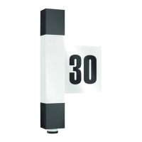
E House number panel
4. Installation / mounting
Preparation
• Select an appropriate mounting location, taking
the reach and motion detection into consideration.
• Switch OFF power supply (Fig. 4.1)
• Ensure correct mounting direction (Fig. 4.2)
Proper operation can only be ensured if the light is
installed vertically.
Wiring diagram (Fig. 4.3)
Connect the mains power supply lead (Fig. 4.6)
The mains power supply lead is a 3-core cable:
L = phase conductor (usually black,
brown or grey)
N = neutral conductor (usually blue)
PE = protective-earth conductor (green/yellow)
If you are in any doubt, identify the conductors
using a voltage tester; then disconnect from the
power supply again. Connect the phase conductor
(L) and neutral conductor (N) to the terminal block.
Important: Incorrectly wired connections will
produce a short circuit later on in the product or
your fuse box. In this case, you must identify the
individual conductors once again and re-connect
them. A mains power switch or a break-contact
button for turning the unit ON and OFF may of
course be installed in the mains supply lead. This
is a prerequisite for the manual override function.
Note: The light source in this light cannot be
replaced. If the light source needs to be replaced
(e.g. at the end of its service life), the complete light
must be replaced.
!
GB