– 10 –
– 11 –
GB
GB
1� About this document
Please read carefully and keep in a safe place�
– Under copyright. Reproduction either in whole or
in part only with our consent.
– Subject to change in the interest of technical
progress.
Symbols
Hazard warning!
...
Reference to other information in the
document�
2� General safety precautions
Disconnect the power supply before
attempting any work on the unit�
• During installation, the electric power cable being
connected must not be live. Therefore, switch o
the power first and use a voltage tester to make
sure the wiring is o-circuit.
• Installing these units involves work on the mains
voltage supply; installation must therefore be
carried out professionally in accordance with
the applicable national wiring regulations and
electrical operating conditions.
(e.g. DE - VDE 0100, AT - ÖVE/ÖNORM E 8001-1,
CH - SEV 1000)
• The LED floodlight must be set to a horizontal
position (±15°).
• The LED floodlight is only intended for wall
mounting and not for ceiling mounting.
• The floodlight enclosure heats up when the light
is on. Only adjust the angle of the LED panel
once it has cooled down.
• Repairs may only be made by specialist work-
shops.
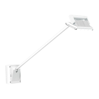
3� LS 150 LED
Proper use
– LED floodlight suitable for wall mounting indoors
and outdoors.
– Fully swivelling LED panel and moveable sensor.
The LED floodlight is equipped with a 240° pyro
sensor which detects the invisible heat emitted by
moving objects (people, animals etc.). The heat
detected in this way is converted electronically into
a signal that switches the floodlight ON. Heat is not
detected through obstacles, such as walls or panes
of glass.
Package contents (Fig� 3�1)
Floodlight adjustment range (Fig� 3�2)
Product dimensions (Fig� 3�3)
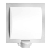
Product components (Fig� 3�4)
A LED floodlight head
B Enclosure
C Wall mount
D Sensor
E Ring cover
F Time setting
G Twilight setting
4� Electrical installation
To obtain the specified reach of 12 m, the sensor
should be installed at a height of approx. 2 m. In-
stall the unit on a firm surface to avoid unintentional
triggering.
The mains supply lead is a 2 to 3-core cable:
L = phase conductor (usually black or brown)
N = neutral conductor (usually blue)
PE = protective-earth conductor (green/yellow)
Wiring diagram (Fig� 4�1)
Important: incorrectly wired connections will
produce a short circuit later on in the product or
your fuse box. In this case, you must identify the
individual cables and re-connect them. A mains
power switch for turning the unit ON and OFF may
of course be installed in the mains supply lead.
Note: the light source in this light must only
replaced by the manufacturer or a service engineer
authorised by the manufacturer or by a similarly
qualified person.
Surface wiring
Underneath the mounting plate you will find two
lugs for surface wiring. Break o one of the two
lugs. Use the sealing plug to close o the cable
opening in the mounting plate. Pierce the sealing
plug and feed the cable through. Once the cable
has been pushed through, you can screw the
mounting plate to the mounting surface and com-
plete the connection. (Fig� 5�7)