– 14 –
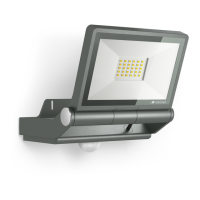
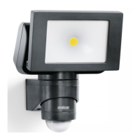
LS150S product components (Fig. 3.8)
A LED panel
B Enclosure
C Wall mount
Technical specifications
– Dimensions (H×W×D):
LS 150 S: 210×155×176mm
LS 150: 178×157×178mm
– Power consumption (P
on
): 14.70W
– Luminous flux (120°): 1375lm
– Half-way angle: 51°
– Eciency: 94lm/W
– Power supply: 220 – 240V, 50/60Hz
– Colour temperature: 4000K (neutral white)
– Average rated life expectancy:
L70B50 at 25°C: 36,000 hours
– Colour rendering index: R
a
= 80
– Colour consistency SDCM: starting value 6
– Luminous intensity distribution:
LumEdit
202103171342_LS150M_Type7757.ldt
Polar Diagram
20.04.21 / 14:53 1/1
100
200
300
400
90°90°
180°
0°
30°30°
150°150°
60°
120°
60°
120°
cd / 1000 lm
C0 / C180 C90 / C270
– Area illuminated to the front: approx. 240cm²
– Sensor technology (SonlyS): passive infrared
– Sensor on standby (P
sb
) (Sonly): 0.50W
– Angle of coverage (Sonly):
240° with 180°angle of aperture
– Sensor unit swivelling range (Sonly): ± 80°
– Floodlight adjusting range:
turns through ± 40°
vertically + 110° to -40°
– Time setting (Sonly): 10s - 15min
– Twilight setting (Sonly): 2-1000lux
– Reach (Sonly): max. 12m
– IP rating: IP44
– Protection class: I
– Impact resistance: IK03
– Ambient temperature: -10°C to +30°C
– Energy ecieny class: this product contains
an energy eciency class "x" light source
4. Electrical installation
Connection
The supply lead is a 2 or 3-core cable:
L = phase conductor (usually black, brown or grey)
N = neutral conductor (usually blue)
PE = protective-earth conductor (green / yellow)
Note:
The protective-earth conductor need not be con-
nected for this product.
Wiring diagram (Fig.4.1)
The light source of this LED floodlight cannot be
replaced. If the light source needs to be replaced
(e.g. at the end of its service life), the complete LED
floodlight must be replaced.
5. Installation
Hazard from electrical power.
Touching live parts can result in electrical shock,
burns or death.
• Switch OFF power and interrupt power supply.
• Using a voltage tester, check to make sure the
light is disconnected from the power supply.
• Make sure power supply remains interrupted.
Risk of damage to property!
Mixing up connection leads may produce a short
circuit.
• Identify connection leads.
• Re-connect connection leads.
Preparing for installation
• Check all components for damage. Do not use
the product if it is damaged.
• Select an appropriate site to install the product.
– Take reach into consideration. (Fig.5.1)
– Take reach and motion detection into consid-
eration. (Fig.5.2, 5.3)
– Vibration-free.
– No obstacles in detection zone.
– Not in explosive atmospheres.
– Not on normally flammable surfaces.
– Do not look into the LED light from a short
distance (<20cm).
– Installing LED floodlight in horizontal
position (±15°).
• Correctly aiming LED floodlight. (Fig.5.4)
Mounting procedure
• Check to make sure the power supply is
switched OFF. (Fig.4.1)
• Unscrew retaining screw. (Fig.5.5)
• Detach enclosure from wall mount. (Fig.5.5)
• Detach plug-in terminal from wall mount.
(Fig.5.6)


 To Next Page