5
7 1/2" MIN.
B
C
D
E
A
3
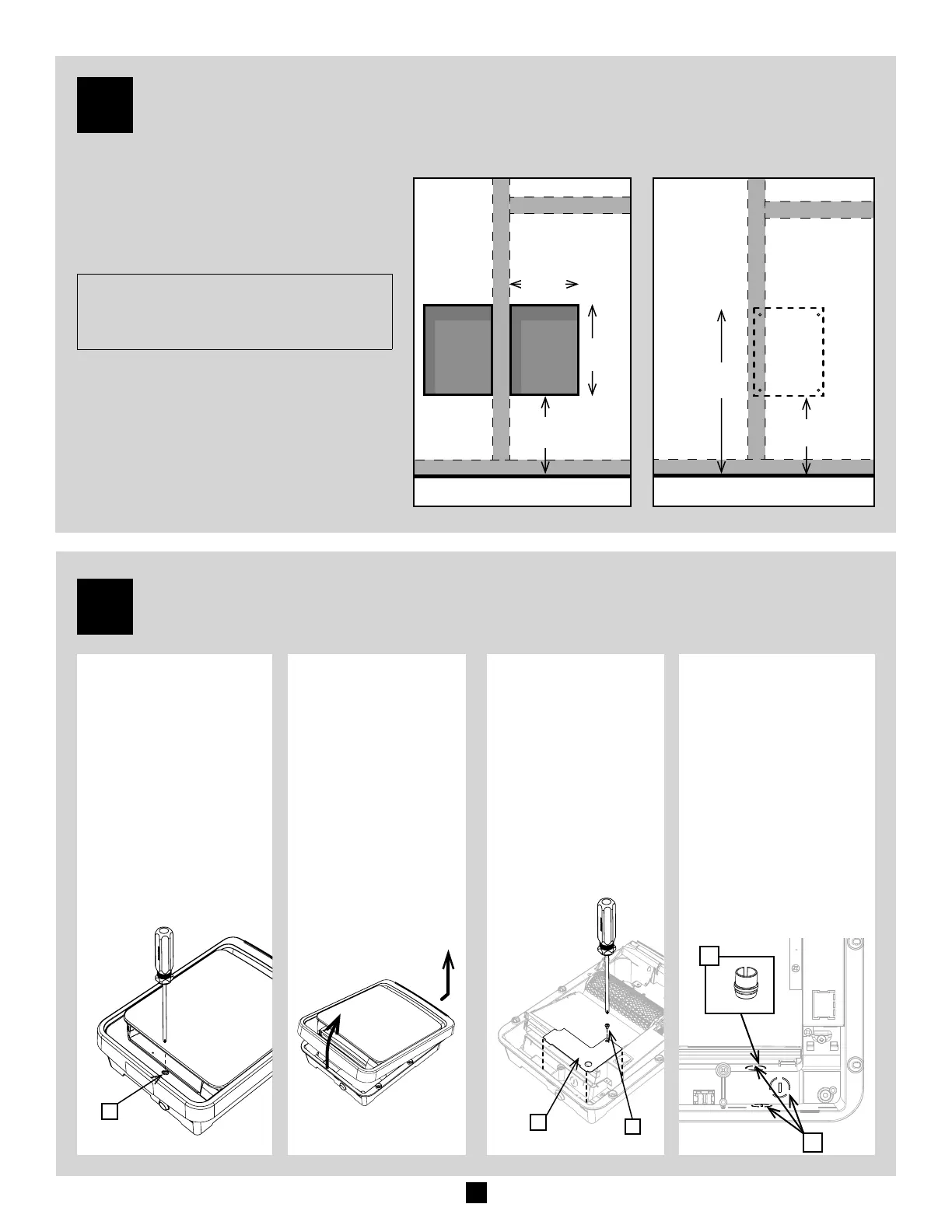
PREPARING THE SURFACE FOR INSTALLATION
7 1/2 in.
(15 cm) min.
21 1/2 in.
(53 cm)
7 1/2 in.
(15 cm) min.
14 in.
(36 cm)
10 1/4 in.
(26 cm)
1. Locate the studs and any other structures that
might be inside the wall.
2. For a recessed installation, make an opening
as shown in the diagram. For a more secure
installation, attach one side of the unit to
a stud.
NOTE: Avoid using an exterior wall for
recessed installations as this decreases the
wall's insulation.
3. To determine where to install the unit on
the wall, use the back box as a guide. For a
sturdier installation, align one side of the fan
heater on a stud, as show in the illustration.
4. Pull the power cable out of the wall. You will
need at least 6 in. of cable inside the junction
box to connect the unit’s wires easily.
FOR A RECESSED INSTALLATION FOR A WALL MOUNT INSTALLATION
4
PREPARING THE FAN HEATER
1. Remove the screw [A]
located at the bottom
of the fan heater and
keep it in a safe place.
3. Remove the screw
[B] and the junc-
tion box cover [C].
Keep them in a safe
place.
2. Swivel the front
panel upwards
as shown in the
illustration to com-
pletely separate it
from the housing.
Place the front of
the fan heater on
a clean surface
where it cannot be
damaged.
4. Punch in one of the
three knockouts [D]
with a at screwdriver.
Choose the hole to
use according to the
position of the power
cable in the wall and
the space available.
5. Place the cable clamp
[E] provided in the
hole you just knocked
out. Insert the power
cable into the cable
clamp.