EasyManua.ls Logo

Step2 BALL BUDDIES Double Drop HQ

Step2 BALL BUDDIES Double Drop HQ
8 pages
To Next Page IconTo Next Page
Loading...
Intended for use by children from ages 12+ months.
OBSERVE ALL STATEMENTS AND WARNINGS TO REDUCE
THE LIKELIHOOD OF SERIOUS OR FATAL INJURY.
SAVE THIS SHEET FOR FUTURE REFERENCE.
CLEANING INSTRUCTIONS
General Cleaning:
Use a 50/50 mixture of white vinegar and water.
Parents should thoroughly wash accessories before use.
DISPOSAL INSTRUCTIONS:
Please recycle when possible. Disposal must be in compliance with
government regulations.
INSPECT THIS PRODUCT BEFORE EACH USE. TIGHTLY SECURE
CONNECTIONS AND REPLACE DAMAGED OR WORN COMPONENTS.
CONTACT THE STEP2 COMPANY FOR REPLACEMENT PARTS.
www.step2.com/survey/?partnumber=498000
1
The Step2 Company, LLC.
10010 Aurora-Hudson Rd.
Streetsboro, OH 44241 USA
1-800-347-8372 USA & Canada Only
(330)656-0440
www.step2.com
BALL BUDDIES
Double Drop HQ
4980
194371A01B08/28/2019
WARNING:
CHOKING HAZARD
Small parts. Adult assembly required.
Question and Answer IconNeed help?

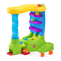
Do you have a question about the Step2 BALL BUDDIES Double Drop HQ and is the answer not in the manual?

Step2 BALL BUDDIES Double Drop HQ Specifications

General IconGeneral
BrandStep2
ModelBALL BUDDIES Double Drop HQ
CategoryToy
LanguageEnglish

Summary

Product Safety and Care

Choking Hazard Warning

Warning about small parts and the need for adult assembly for children 12+ months.

General Safety and Inspection

Follow all warnings to reduce injury risk and inspect product before each use.

Cleaning Instructions

Use a 50/50 mixture of white vinegar and water for general cleaning.

Disposal Instructions

Recycle when possible, adhering to government regulations.

Assembly Instructions

Step 1: Connect E and A

Assemble part E onto part A, applying pressure for secure fit.

Step 2: Install DL and DR

Insert the DL and DR components into the designated slots.

Step 3: Secure DL and DR

Fasten DL and DR components using x8 1/2" screws.

Step 4: Attach G to D and A

Connect part G to part D and then attach to part A.

Further Assembly Steps

Step 5: Attach Base Components

Attach components using x2 3/4" screws as shown.

Step 6: Install Side Panels

Insert and secure three F parts into part C using x12 3/4" screws.

Step 7: Attach C to Base

Mount part C onto the main base assembly (part A).

Step 8: Secure C with Screws

Fasten part C to the base using x4 1-1/4" screws.

Final Assembly Stages

Step 9: Secure Top Structure

Attach the upper section to the base using x7 1-1/4" screws.

Step 10: Install Part H

Insert part H into its designated position.

Step 11: Attach Part B

Mount part B onto the assembled structure.

Step 12: Insert Part J

Place part J into the opening at the top.

Completion and Final Steps

Step 13: Final Rotation

Rotate the top track piece to its final position.

Step 14: Secure Top Track

Secure the top track assembly with x3 1-1/4" screws.

Related product manuals