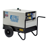
SSD6000-SSD6000S-SE6000D4
7
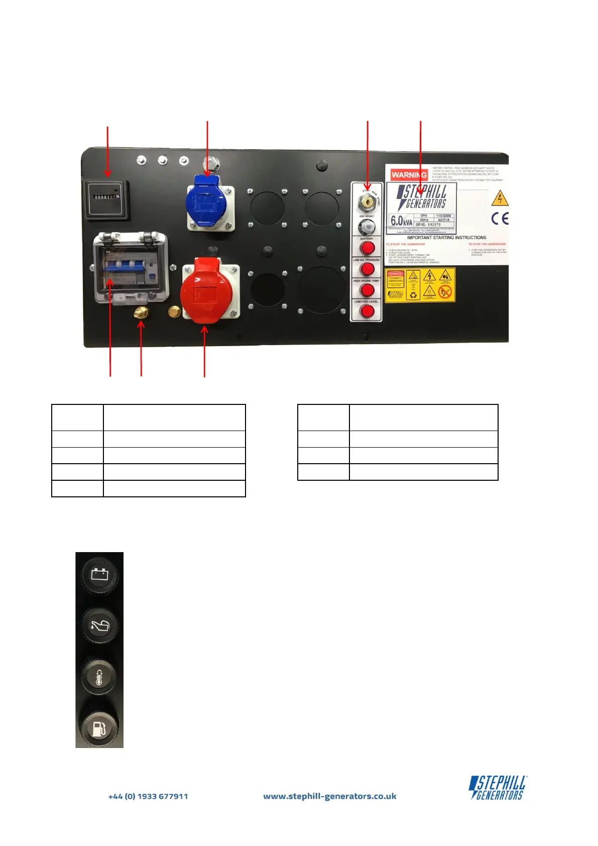
Fig.4 below shows a typical example of a standard 3 Phase control panel.
1
Hours Run Meter
5
RCBO - 4 pole
2
230V 1Ph Socket Outlet (Blue)
6
Earth Stud - M8
3*
Key Switch & DC Reset Button
7
400V 3Ph Socket Outlet (RED)
4
Serial Data Plate
* The Warning & Shutdown Lamps description can be
found in Operating Instructions . These are LED
lamps.
Fig.3 shows the previous version of the Warning & Shutdown lamps. These operate
exactly the same as the current versions shown in Fig.2 & Fig.4 but are not LED.
IMPORTANT: It is highly recommended to periodically check and test the 12V bulbs in
the lamp holders as shown in Fig.3. A faulty bulb can inhibit basic fault finding.