29
ATTACH THE ELEMENTS TO THE EHU’s (continued)
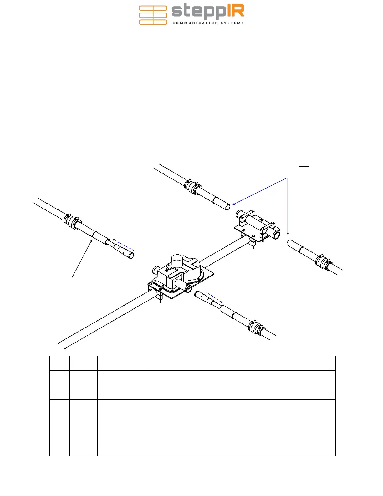
SECURING THE ELEMENT SUPPORT TUBE (EST) TO THE EHU
When the CPVC inner guide tubes are completed, they will need to be inserted into the telescoping
poles and secured to each EHU. Figure 7.10 below gives an overview of this procedure, with detailed
instructions following on the next page.
This drawing shows the EHU placement for the Reflector element, the procedure is the same for the
Director and Driven elements. The parts required in the table below are shown for EACH complete loop
assembly.
Key QTY Part # Description
A 4 10-1006-22 Quick disconnect boot
B 4 10-1013-02 Telescoping pole
C 2 NA Inner guide tube assembly consisting of diverter cone , 39-
7/8” and 49” CPVC Plastic tube, glued together. They are
only used on the EHU side of the 40/30 loop
D 4 NA Quick disconnect boot locking ring (these are molded into
the base section of each telescoping pole and are used to
keep the pole from sliding out of the quick disconnect boots
in high wind situations)
A
A
A
A
B
B
B
B
C
Inner guide tube not required
for the return side of the 40/30
loop
C
D Quick disconnect boot
locking ring
FIG. 7.10