EasyManua.ls Logo

Sterling Power Products BB1230 User Manual

Sterling Power Products BB1230
13 pages
To Next Page IconTo Next Page
Page #1 background imageLoading...
Page #1 background image
Sterling Power Products
Copyright
STERLI
G
POWER
Pro Batt Ultra - Battery to Battery Charger
Copyright © 2016
Sterling Power
V 2.6 June 2016
Starter
Engine Bat.
Pos
in
Pos
out
Neg
fuse
fuse
House / Domestic / Aux
/ Bow thruster
Main Power
Terminals
MUST READ
For the vast majority of users (90%+) reading this paragraph should
be sufficient for installation. The unit can be installed by simply
installing it between an input and output battery as depicted. The
unit, by default, shall start charging when the input voltage exceeds
13.6V and switch off when the voltage drops below 13.3V for more
than 120s (adjustable). Going above 13.6V for 5 seconds shall reset
this timer . The default charging profile is 14.4V abs. and 13.6V float -
for sealed lead acid batteries. (x2 for 24V | x3 for 36V | x4 for 48V). this
means that the vast amount off installations can be fitted out off the box
without any adjustments.
If charging is required when your vehicle is stationary you may require
lower than 13.6V input in order to activate. Please read about the
Stationary vehicle engagement mode later in the manual.
Code:
BB1230
12V-12V 30A input
BB122440
12V-24V 40A input
battery temp
sensor
USERS MANUAL.
Sterling Power Products
H Charge
Float
In / Unit
Out / Rem
Batt.
V
12.2
Temp
Menu
Change
Volts
Select
Audible alarm on/off
hold > 3 sec
On / Off
hold>3 sec
Fault
Absorption
Cond.
Optional Remote
Instructions inside
technology
4
D
U
:
L
R
A
A
T
I
B
G
L
I
E
D
:
:
D
C
I
E
S
M
I
A
G
N
N
Y
D
ProDigital
RoHS
compliant
R.B.F
Regenerative
raking riendly B F
Test Report Sheet
Each product gets uniquely tested and a report is generated.
This unique test report is present inside this box.
You must keep this test sheet in this box and keep this box safe.
This sheet should be present when the charger is being warranted.
*default mode does not require ignition feed*
Code:
BB1260 12V-12V 60A input
BB122470 12V-24V 70A input
BB123670 12V-36V 70A input
BB124870 12V-48V 70A input
BB242435 24V-24V 35A input
BB241235 24V-12V 35A input
BB123670 12V-36V 70A input
BB124870 12V-48V 70A input
+
+
+
Please read the legal and safety
information first before proceeding
and we strongly advise hiring a
professional to fit.
Question and Answer IconNeed help?

Do you have a question about the Sterling Power Products BB1230 and is the answer not in the manual?

Sterling Power Products BB1230 Specifications

General IconGeneral
BrandSterling Power Products
ModelBB1230
CategoryBattery Charger
LanguageEnglish

Summary

Test Report Sheet

Must Read Installation Guidelines

Product Specifications Overview

Legal and Safety Information

Using the Instruction Manual

Guidance on how to read and follow the manual for proper device use.

Warranty Statement Details

Information and terms regarding the product's warranty coverage.

Copyright and Plagiarism Policy

Details concerning the document's copyright and reproduction restrictions.

Manufacturer Liability Disclaimer

Statement outlining limitations of manufacturer's liability.

Device Modification Warnings

Caution against unauthorized modifications and warranty voidance.

Proper Charger Usage Conditions

Specifies correct conditions and environments for charger operation.

Safety Symbols Explanation

Explanation of various warning and caution symbols used.

General Maintenance and Repair

Instructions for performing maintenance and repairs on the device.

General Safety and Installation Precautions

Essential precautions for safe installation and operation of the unit.

Battery Safety Guidelines

Specific safety advice and precautions related to battery handling.

Front Panel Interface

Front Label and Button Layout

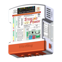
Explanation of labels, buttons, and indicators on the front panel.

LED Indicator Status Meanings

Detailed meanings of various LED indicators for operation and faults.

Front Panel Details and Connections

Under the Lid Components

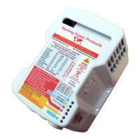
Description of components and connections located under the unit's lid.

Recommended Cable Sizing

Guidance on selecting appropriate cable sizes for current requirements.

Quick Installation Guide

Operational Mode Selection

Description of the different operational modes for the charger.

Front Panel Button Quick Guide

Summary of front panel button functions for quick reference.

Temperature Sensor Installation

Instructions for connecting and utilizing the optional temperature sensor.

Basic Operation and Installation

Auxiliary Control Terminal Connections

Wiring details for auxiliary control terminals.

Wiring Connection Scenarios

Instructions for various wiring configurations and connections.

Detailed Operational Modes

In-depth explanation of the three operational modes.

First Time Use and Setup

Initial Startup and Calibration Checks

Procedures for the initial startup and checks for calibration issues.

Changing Charging Profile at Startup

How to select or change battery charging profiles during initial setup.

Interpreting Meter Readings

Understanding input and output voltage displays and LED indicators.

Handling Out of Range Voltages

Explanation of LED indications for voltage values outside normal ranges.

Troubleshooting Voltage Issues

Diagnosing and resolving low or high output voltage conditions.

Advanced Force Options

Regenerative Braking Timer Adjustment

Configuring the timing for regenerative braking.

Checking Charger Status

How to view the current operational status of the charger.

Operating as a Power Pack

Using the unit as a power supply without an output battery connected.

Forcing Float Mode

Manually locking the charger into float charging mode.

Forcing Unit On/Off

Procedure to manually turn the charger unit on or off.

Half Power Operation Mode

Reducing the unit's power output to approximately 50%.

Night Mode (8 Hour Half Power)

Activating reduced power and fan speed for a limited 8-hour period.

Cutoff Voltage Impact on Auto Regen

Note on how cutoff voltage changes affect auto regen reset.

Stationary Vehicle Engage Mode (SVEM)

Mode for stationary use, allowing engagement at lower input voltages.

Custom Battery Settings

Adjusting Fast Charge / Bulk / Absorption Voltage

Setting the primary charging voltages for different battery types.

Adjusting Conditioning Charge Voltage

Setting the intermediate charge voltage level.

Adjusting Float Charge Voltage

Setting the final maintenance charge voltage.

Adjusting Absorption Time Factor

Modifying the absorption phase duration using a time factor.

Understanding Absorption Time Factor (ATF)

Explanation of the ATF's purpose and calculation for absorption time.

Custom Voltage Adjustments

Adjusting Minimum Absorption Time

Setting the minimum duration for the absorption charging phase.

Adjusting Maximum Absorption Time

Setting the maximum duration for the absorption charging phase.

Adjusting Core Operational Voltages

Adjusting charging, cutoff, and low voltage trip parameters.

Charging Voltage Setting

Setting the voltage at which the charger initiates charging.

Cutoff Voltage Setting

Setting the voltage at which the charger will stop charging.

Lower Voltage Trip (Mode 3) Setting

Setting the low voltage threshold specific to operational mode 3.

Remote Control Operation

Volts Select Button Functions

Detailed functions of the left 'Volts Select' button.

Combined Button Operations

Functions achieved by pressing both left and right buttons.

Temperature Menu Change Button

Functions of the right 'Temp Menu Change' button.

Remote Control Setup Menu

Navigating and utilizing the remote control's setup menu.

Remote Control Error Codes

List and explanation of error codes displayed on the remote unit.

Fault Finding and Troubleshooting

Voltage Discrepancies (No Load)

Troubleshooting voltage issues when no loads are connected.

Low Output Voltage Diagnosis

Diagnosing low output voltage with a healthy input voltage.

Low Input Voltage Diagnosis

Troubleshooting scenarios involving low input voltage.

LED 16: Input Over-Voltage

Interpreting the red flashing LED 16 for input over-voltage.

LED 16: Output Over-Voltage

Interpreting the solid red LED 16 for output over-voltage.

LED 17: Unit Over-Temperature

Interpreting the flashing red LED 17 for unit over-temperature.

LED 21: Output Cable Voltage Drop

Interpreting yellow flashing LED 21 for output cable voltage drop.

LED 22: Half Power Mode Indication

Interpreting yellow LED 22 for half power mode engagement.

LED 23: Undervoltage Indication

Interpreting yellow LED 23 for undervoltage conditions.

LED 24: High Battery Temperature

Interpreting flashing red LED 24 for high battery temperature.

Related product manuals