7
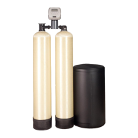
STEP 1: If media is already loaded in filter tank proceed to Step 4. Otherwise, use the fillport wrench
provided to remove the fillport cap (Refer to Figure 2) by turning it counter-clockwise.
STEP 2: DO NOT REMOVE THE WHITE FILLPORT SCREEN! Use the fill funnel provided to add the
required amount of media (see unit specifications) to the filter tank. Do not overfill the tank. At
least 14” of freeboard (empty space) is required at the top of the media tank to allow for proper
bed expansion during backwash. Any excess media may be saved for future replenishment.
STEP 3: Clean any media out of the fillport cap threads. Do not reinstall the fillport cap until Step 9.
STEP 4: Place softener tank on right side with inlet/outlet facing left. Place filter tank on left with
inlet/outlet facing right.
STEP 5: Attach the control valve assembly to the front inlet opening of the filter tank and outlet opening
of the softener tank. Attach the straight pipe adapter to the back outlet of the filter tank and
inlet of the softener tank. HAND TIGHTEN UNION NUTS ONLY. DO NOT OVERTIGHTEN.
Installation Instructions
FIGURE 2: Tank Positioning and Fillport Location
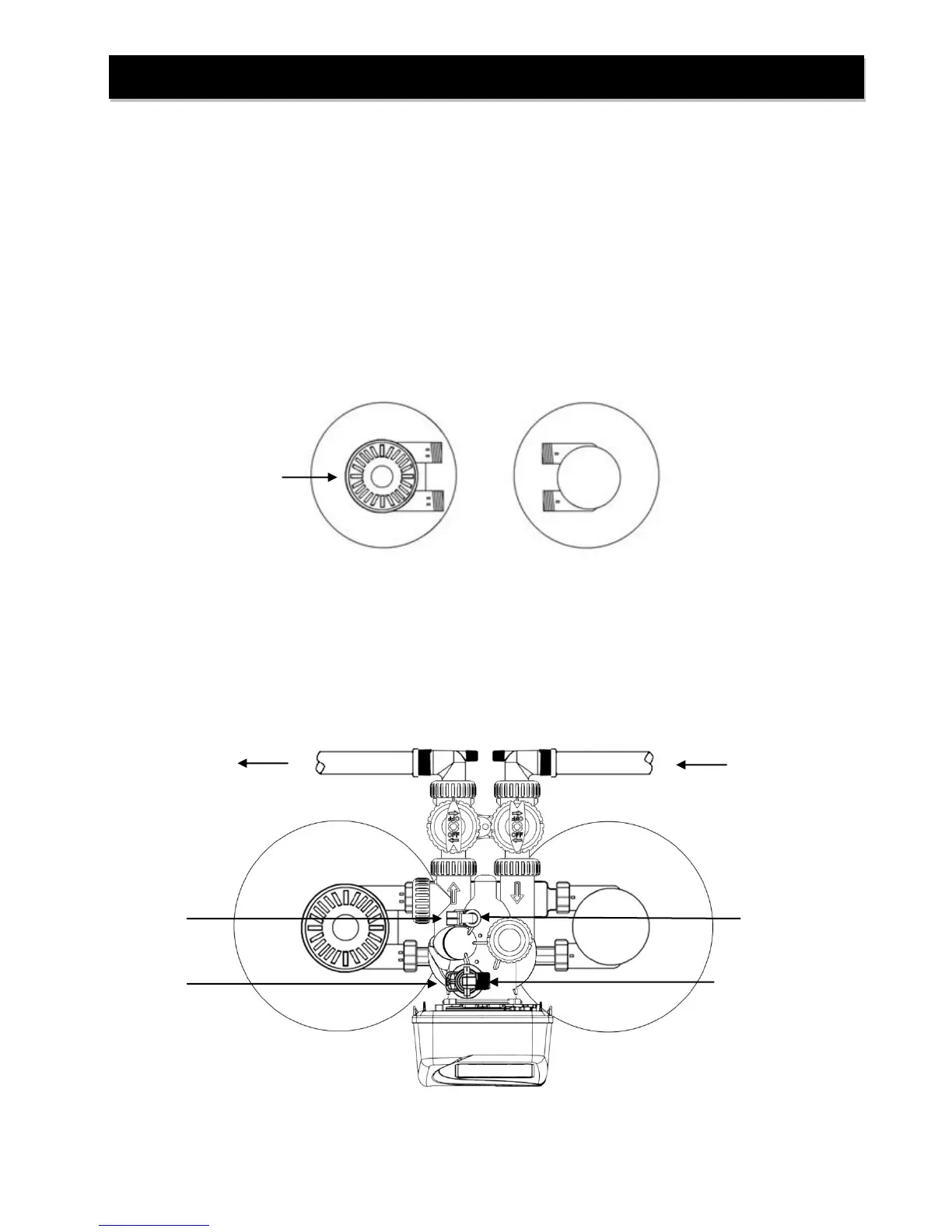
FIGURE 3: Top View of IFS10
Drain Line Flow Control Assembly
(DLFC Elbow Fitting not shown)
Brine Refill Elbow and
Brine Line Flow Control
Assembly
 Loading...