20
IN GND SW OUT
R3
R2R1
R10
R4
D1
CLEAN
BIAS
C3
Q2
C1
C2
C6
Q1
503 1E
502 9L
WD 08
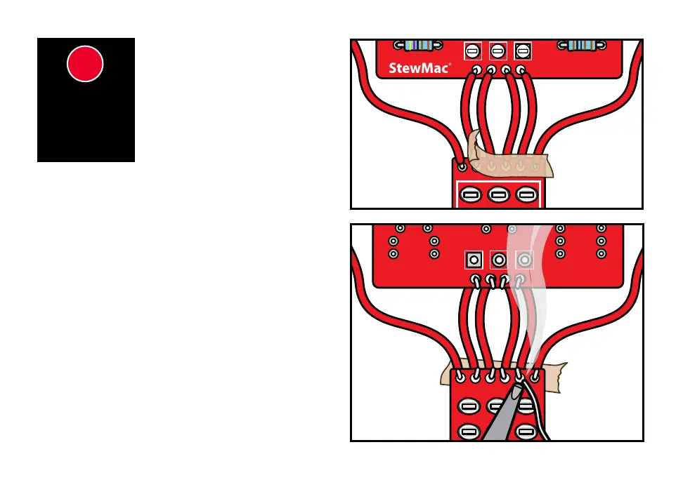
Align the PCB and breakout board component side
up. Guide the leads of the
2.5” wires coming from the
bottom of PCB through the holes in the breakout board.
Next, cut two 4” pieces of the remaining 22 gauge
wire and strip 3/32” o both ends of both wires. Insert
one end of each wire into the remaining holes on the
breakout board and tape the leads to the breakout
board on the component side to prevent them from
slipping out of the holes.
Carefully ip the PCB and breakout board over and
solder all the wires in place on the solder side of the
boards. Once the solder has cooled, remove the tape.
SOLDER
BREAKOUT
BOARD TO
THE PCB
88
Now we’re going to attach the
breakout board to the PCB, as
well as attach the wires to the
breakout board that will connect
to the pots. Have a small piece of
masking tape on hand.
 Loading...