25
Remove the nuts and
washers again from
the pots and
footswitch and lay
the pedal housing
face down. With the
component side of the
PCB facing up, carefully insert the shafts
of the pots and footswitch into their holes.
Reattach the washers and nuts using a 10mm wrench
for the pots, and 14mm wrench for the switch.
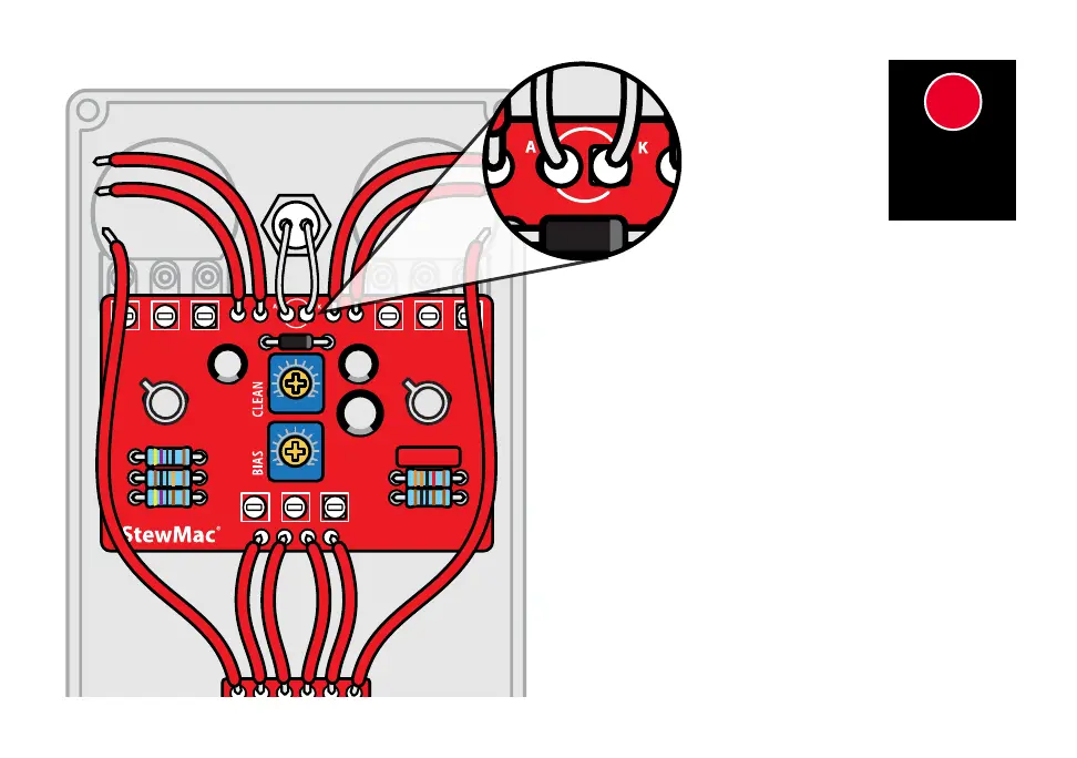
To connect the LED, thread the longer positive lead
through the hole marked “A” and the shorter negative
lead through the hole marked “K” on the component
side of the PCB and solder in place. Use care to make
sure these bare leads are not touching one another or
the LED will malfunction.
Twist the pot shafts all the way counter-clockwise and
install the knobs pointing at “7 o’clock” indicating their
“zero” position.
1313
INSTALL
CIRCUIT
BOARD
 Loading...