STid reserves the right to make change without notice, for the purpose of product improvement.
Relay
Read-only reader, except touch screen: automatic tamper management.
Touch screen read-only reader: if the bell is activated, contact J2 is used to connect the external ring (max. 200 mA at 28 Vdc).
Read/Write reader: the relay is controlled by the SSCP/OSDP™ protocol commands.
UHF default configuration settings
Reader powered off. The default reader settings can be stored in internal memory accessible by UHF RFID technology. They will be taken into account when the
reader is powered on.
Read-only reader configuration
R and S readers are configurable with the SCB configuration card or virtual configuration card created with SECard.
▪ If the SCB is compatible with the reader’s firmware, the LED lights green and the buzzer beeps five times.
▪ If the SCB is not compatible with the reader’s firmware, the LED lights red and the buzzer is activated for 1 s.
Caution: set your reader with your own company key.
Powering-up the readers
On power-up, the reader enters an initialization phase:
1. Activation of the white LED and buzzer for 100 ms.
For read-only readers:
2. Activation of the LED, according to the color code: Red = +10, Orange = +5, Green = +1, indicating the firmware version.
3. For serial R/S ARC only: the orange LED flashes 20 times: waiting for an update.
4. For ARCS Blue only: Activating white fixed LED during Bluetooth initialization.
5. Activation of the default LED (flashes blue if no customer specific configuration).
6. ARC Screen: display of the default image and keypad activation by touching the screen.
Precautions for the biometric sensor and keypad
▪ For optimal operation, the biometric sensor must be free of all traces of water. Outdoors it is recommended to install the reader under cover.
▪ The keypad is sensitive. Take off your gloves to enter your code.
▪ For the ARC screen with an activated keypad, the default mode is: display the picture on standby and activate the keyboard by pressing the screen.
Caution for Bluetooth reader
▪
Caution: at the reader Bluetooth (BT1/BT2) powering, make sure that nothing is in an area of at least 10 cm / 3.94 in. around the reader (ex.
No hand in front of the reader…).
Precautions for installation
▪ The supply voltage at the reader’s connector should be between +7 Vdc and +28 Vdc.
▪ As far as possible, keep the reader away from computer or power source cables. They can generate electrical interference, depending on their radiation level
and the proximity of the reader.
▪ Recommended distance between two readers: parallel plane: 15.8 in – same plane: 15.8 in – perpendicular plane: 11.8 in.
▪ Recommended distance between two Blue readers: 2 meters either plan.
▪ Readers installed on a metal surface may have reduced performances.
▪ Use a ferrite (two-way) for the cable (power supply and data). Example: reference 74271222 WURTH ELEKTRONIK.
▪ For ARCS screw terminal output reader, connect the 2.2 µF capa (provided) between +12V and GND directly to the output of the connector (no polarization).
▪ By design, the reader can be installed indoors and outdoors.
▪ Disconnect the wires or the connector of the reader BEFORE powering on or off.
▪ Operating temperature: Readers A, B, C, I and J: -4 °F to 158 °F / -20°C à +70°C
Readers D, E and F: -14 °F to 122 °F / -10°C à +50°C
TTL pull-ups
For data signals, 10k pull-up resistors are connected internally to V
in
(power supply voltage) for optimal wiring distances.
RS232 / RS485 communication
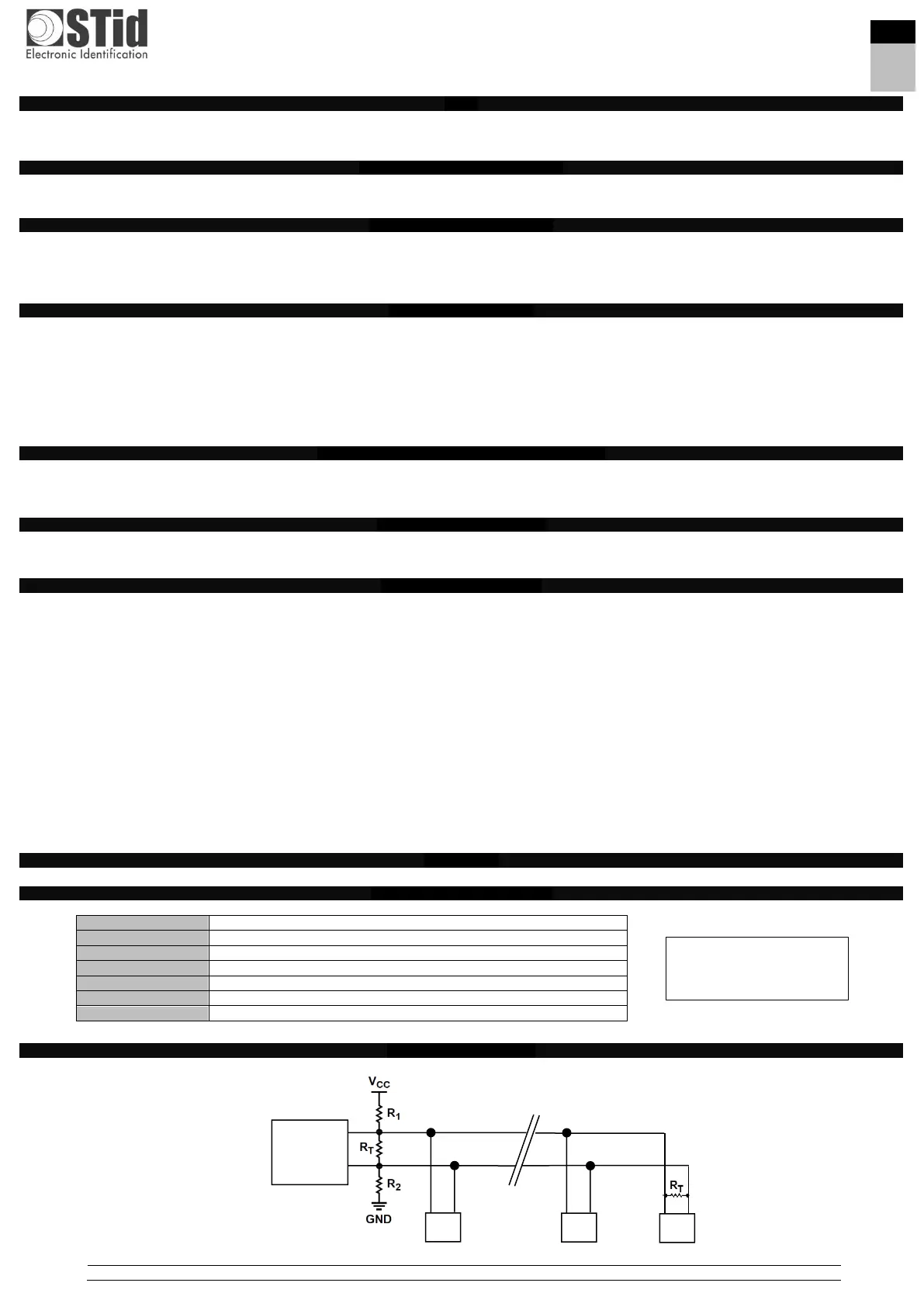
Bus architecture (RS485)
Wiring resistors R1 and R2 use extended features of the RS485 bus: FAIL-SAFE (see RS485-AN-960).
R1 & R2: 1.5 kΩ resistor not supplied.
R
T
: 120 Ω end-of-line resistor supplied
 Loading...