Power supply characteristics
Use an AC/DC power supply type LPS, Limited Power Source (as per IEC EN 60950-1 Ed2) or type ES1, PS1 (according to IEC EN 62368-1) for the main
supply.
Main power supply: Range: +7 Vdc to +28 Vdc Typical: 12 Vdc
Max. consumption at 12 Vdc:
ARCS-A/PH5: 140 mA ARCS-C/PH5: 210 mA ARCS-E/PH5: 320 mA ARCS-I/BF5: 170 mA
ARCS-B/PH5: 170 mA ARCS-D/PH5: 290 mA ARCS-F/PH5: 360 mA ARCS-J/BF5: 200 mA
ARCS-A/BT1: 150 mA ARCS-C/BT1: 220 mA ARCS-E/BT1: 330 mA ARCS-I/BT2: 180 mA
ARCS-B/BT1: 180 mA ARCS-D/BT1: 300 mA ARCS-F/BT1: 370 mA ARCS-J/BT2: 210 mA
Characteristics
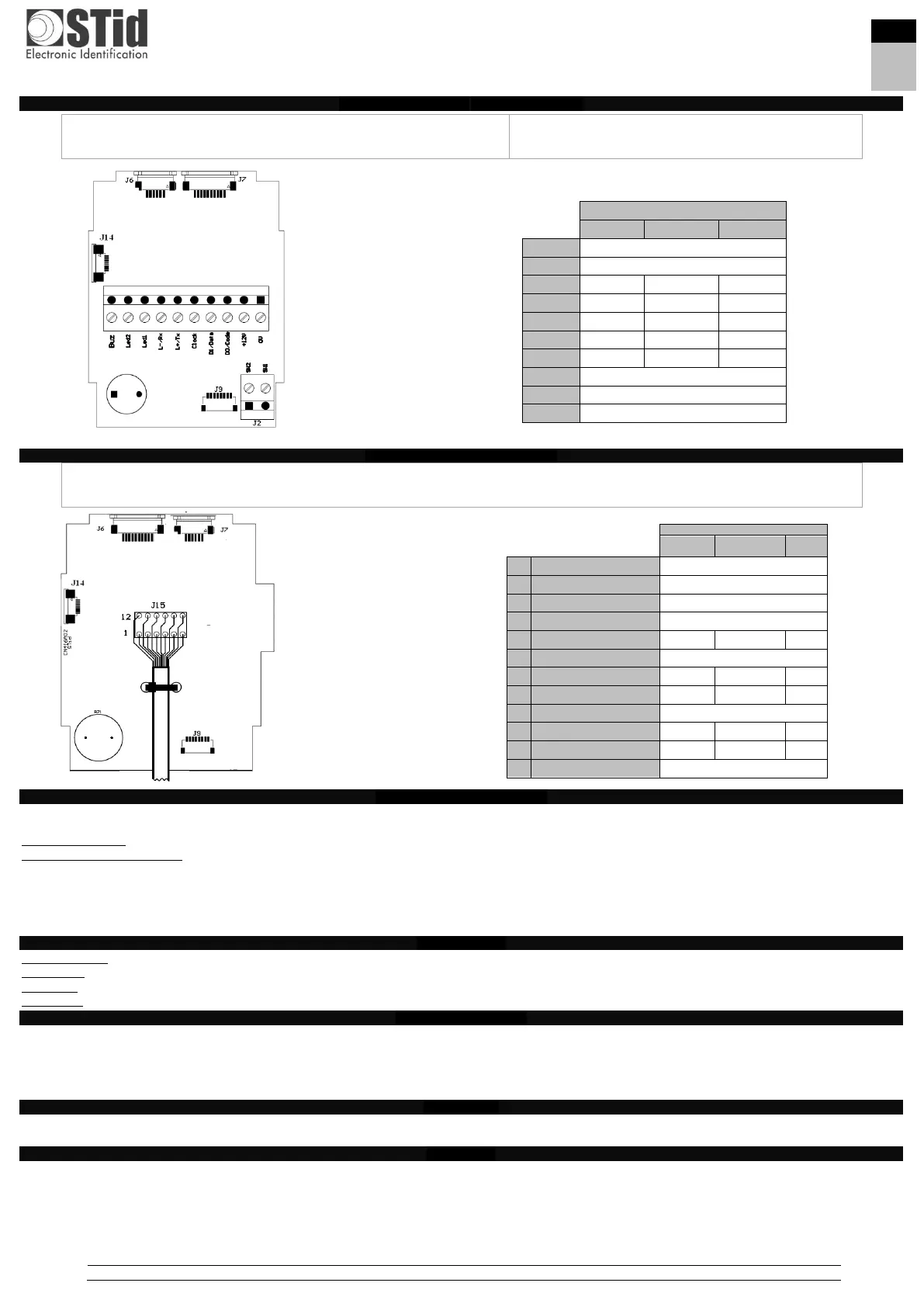
Communication: RS485 (L+ & L-) / TTL (Wiegand / Clock and Data)
Connection: Removable connectors 1x10 pins and 1x2 pins, thread 0.19685 inch OR cable.
Protection: IP65, excluding connectors
Static relay: ASSR-1218-003E: 60 V output withstand voltage / 0.2A current rating / low on-resistance 1 Ω typical for AC/DC
Recommended cables
▪ Screw terminal output: Use a multi-conductor shielded twisted pair cable.
Max. length RS485: 328.1 ft at 9600 baud
Wiegand / Clock & Data: 1 pair AWG24 – 98.4 ft max / 2 pairs AWG24 – 196.9 ft max / 3 pairs AWG24 – 328.1 ft max
1 pair AWG20 – 164.0 ft max / 2 pairs AWG20 – 328.1 ft max
▪ Cable output (cable supplied): TRANXALARM - 14x0.22mm2 - lg 3,05m.
Buzzer / LED
The operating mode for the Buzzer and LED 1 and 2 can be programmed by a configuration card (R3x & S3x) or controlled by the remote system with a 0 Vdc
respectively on the “Led 1”, “Led 2” and “Buzzer” inputs of the reader’s connector or controlled by the communication protocol of the reader (W3x).
Anti-tearing
Tearing is detected by an accelerometer. When the reader is wrenched, the switch output (connector J2) provides an O/C contact to indicate the tearing of
reader.
▪ for R/S 31: the wrenching signal will be emitted on the “Data/Data1” line. This function is configurable via a configuration card.
▪ for R/S 33: the reader will perform the operations configured with the configuration card.
▪ for W33: the reader will perform the operations configured with the SSCP protocol.
Caution: switch on the reader when it is in its final position to initialize the accelerometer in the correct position.
 Loading...