18 |CNS UT WWW.STIEBEL-ELTRON.COM
INSTALLATION
SPECIFICATION
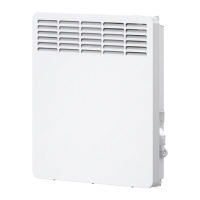
12. Specification
12.1 Minimum distances / connections and dimen-
sions
b01
a20
i13
D0000019277
CNS
50 UT
CNS
75 UT
CNS
100 UT
CNS
125 UT
CNS
150 UT
CNS
200 UT
CNS
250 UT
CNS
300 UT
a20 Appliance Width mm 370 445 445 590 590 740 890 1040
b01 Grommet for electrical cables
i13 Wall mounting bracket Hole spacing mm 121 195 195 343 343 491 639 787
12.2 Data table
CNS 50 UT CNS 75 UT CNS 100 UT CNS 125 UT CNS 150 UT CNS 200 UT CNS 250 UT CNS 300 UT
231547 231548 231549 231550 231551 231552 231553 231574
Electrical details
Connection output kW 0.5 0.75 1.0 1.25 1.5 2.0 2.5 3.0
Power connection 1/N 230 V 50 Hz 1/N 230 V 50 Hz 1/N 230 V 50 Hz 1/N 230 V 50 Hz 1/N 230 V 50 Hz 1/N 230 V 50 Hz 1/N 230 V 50 Hz 1/N 230 V 50 Hz
Dimensions
Height mm 450 450 450 450 450 450 450 450
Width mm 370 445 445 590 590 740 890 1040
Depth mm 100 100 100 100 100 100 100 100
Weights
Weight kg 3.3 4 4 5.2 5.2 6.3 7.7 8.9
Versions
Frost protection setting °C 7 7 7 7 7 7 7 7
Version 24 h quartz time
switch
24 h quartz time
switch
24 h quartz time
switch
24 h quartz time
switch
24 h quartz time
switch
24 h quartz time
switch
24 h quartz time
switch
24 h quartz time
switch
IP rating IP24 IP24 IP24 IP24 IP24 IP24 IP24 IP24
Protection class II II II II II II II II
Colour alpine white alpine white alpine white alpine white alpine white alpine white alpine white alpine white
Values
Setting range °C 7-30 7-30 7-30 7-30 7-30 7-30 7-30 7-30
A10 Appliance Height mm 450
A30 Appliance Depth mm 100
A50 Appliance Minimum top clearance mm 250
A51 Appliance Minimum bottom clearance mm 100
A52 Appliance Minimum r.h. clearance mm 100
A53 Appliance Minimum l.h. clearance mm 100
A54 Appliance Minimum front clearance mm 500
A55 Appliance Minimum rear clearance mm 22
 Loading...
