www.stiebel-eltron.com SHZ S (GB) | 9
INSTALLATION
Troubleshooting
14. Troubleshooting
Note
The high limit safety cut-out can respond at temperatures
below –15°C. The appliance may be subjected to these
temperatures during storage or transport.
Fault Cause Remedy
The water does not heat
up.
The high limit safety
cut-out has responded
because the controller is
faulty.
Remedy the cause of
the fault. Replace the
controller-limiter com-
bination.
The high limit safety
cut-out has responded
because the temperature
has fallen below -15°C.
Press the reset button
(see diagram).
The rapid heat-up does
not switch on.
Check the button and
lever.
The flanged immersion
heater is faulty.
Replace the flanged im-
mersion heater.
The selected outlet tem-
perature is not reached
during manual rapid
heat-up operation when
the draw-off valve is fully
opened.
More water flows
through the appliance
than the heating element
can heat up.
Reduce the flow rate at
the DHW valve.
The safety valve drips
when heating is switched
off.
The valve seat is con-
taminated.
Clean the valve seat.
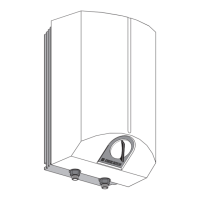
High limit safety cut-out reset button
The reset button is located behind the temperature selector.
Pull off the temperature selector.
D0000047866
12
1 Reset key, high limit safety cut-out
2 Thermostat/limiter combination
15. Maintenance
WARNING Electrocution
Before any work on the appliance, disconnect all poles
of the appliance from the power supply.
For some maintenance work you must remove the bottom cap.
If you also need to drain the appliance, observe chapter "Draining
the appliance".
15.1 Checking the safety assembly
Regularly check the safety assembly.
15.2 Draining the appliance
WARNING Burns
Hot water may escape during the draining process.
If the cylinder needs to be drained for maintenance or to protect
the whole installation when there is a risk of frost, proceed as
follows:
Close the shut-off valve in the cold water line.
Open the hot water taps on all draw-off points.
26�02�07�0163
1
1 Drain valve cap G 1/2
Undo the cap of the drain valve connection.
15.3 Replacing the protective anode
When replacing the anode, take great care not to fit the pres-
sure switch too tightly.
Observe spanner size 13 of the anode and the maximum transition
resistance of 0.1 Ω between the protective anode and the cylinder
connection.
15.4 Descaling
Only descale the flange after disassembly and never treat the
cylinder surface and protective anode with descaling agents.
15.5 Anti-corrosion protection
Ensure when carrying out service work that the anti-corrosion
protection on the insulating plate is not damaged or removed.
Reinsert the anti-corrosion protection correctly after replacement.
1
4
2
3
D0000048051
1 Corrosion resistor (390 Ω)
2 Pressure plate
3 Insulating plate
4 Copper flanged immersion heater
 Loading...