www.stiebel-eltron.com WPL 33 | 7
INSTALLATION
Safety
INSTALLATION
7. Safety
Only a qualified contractor should carry out installation, commis-
sioning, maintenance and repair of the appliance.
7.1 General safety instructions
We guarantee trouble-free function and operational reliability only
if original accessories and spare parts intended for the appliance
are used.
7.2 Instructions, standards and regulations
Note
Observe all applicable national and regional regulations
and instructions.
8. Appliance description
For outdoor installation the appliance offers additional frost pro-
tection of the heating water pipes. The integral frost protection
circuit starts the heating circuit pump in the heat pump circuit
automatically at +8°C condenser temperature, and thereby en-
sures circulation in all water-filled sections.
The heat pump starts automatically when the temperature in the
heat pump circuit drops below +5°C.
In dual mode operation, return water from the second heat gen-
erator may flow through the heat pump. The return water tem-
perature must not exceed 60 °C.
8.1 Standard delivery
The casing components for the appliance are delivered in a sep-
arate pack.
8.1.1 Standard appliance
- Type plate
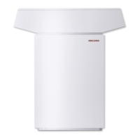
8.1.2 Casing components – outdoor installation
- Hood – outdoor installation
- Front panel
- Back panel
- Pipe bend, heating circuit flow
- Pipe bend, heating circuit return
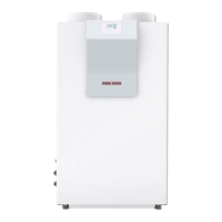
8.1.3 Casing components – indoor installation
- Hood – outdoor installation
- Front panel
- Back panel
- Pipe bend, heating circuit return
8.2 Required accessories
8.2.1 Required accessories for outdoor installation
- Heat pump manager WPM
- Accessories – outdoor installation
- Pressure hoses SD25 or SD32
8.2.2 Required accessories for indoor installation
- Heat pump manager WPM
- Accessories – indoor installation
- Pressure hoses SD25 or SD32
8.3 Further accessories
8.3.1 Further accessories for outdoor installation
- Remote control for heating systems FE7
- Remote control for heating systems FEK
- Water softener HZEA
8.3.2 Further accessories for indoor installation
- Air hose DN560 x 4 m
- Hose connection panel 560
- Wall outlet AWG 560 H
- Wall outlet AWG 560 V
- Wall outlet AWG 560 L
- Wall outlet AWG 600 L
- Remote control for heating systems FE7
- Remote control for heating systems FEK
- Condensate pump PK 10
- Water softener HZEA
9. Preparations
9.1 Sound emissions
The appliance is louder on the air intake and air discharge sides
than on the two enclosed sides. Observe the following information
when selecting the installation location.
Note
For details regarding the sound power level, see chapter
"Specification / Data table".
9.1.1 Sound emissions for outdoor installation
- Lawn areas and shrubs help reduce the spread of noise.
- Noise propagation can also be reduced through dense pali-
sades or similar.
Ensure that the air intake direction is the same as the dom-
inant wind direction. Air should not be drawn in against the
wind.
Never direct the air intake or discharge towards noise-sensi-
tive rooms of the house, e.g. bedrooms.
Avoid installation on large, echoing floor areas, e.g. tiled
floors.

 Loading...


