29Series 4144 Powerhead
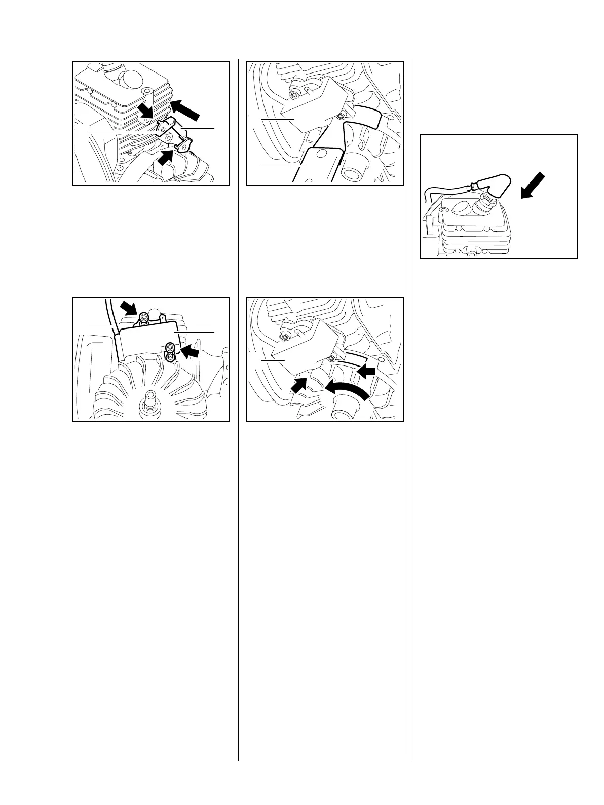
– Position the insulator (1) so that
the connecting bar (2) points
towards the carburetor.
: Attach the lugs (arrows) of the
insulator (1) to the bosses.
: Place the ignition module (1) in
position so that the ignition lead
(2) faces the muffler and insert
the screws (arrows) with washers
– do not tighten down yet.
2
1
938RA082 TG
1
2
938RA083 TG
– Push the ignition module (1) back
: Slide the setting gauge (2)
1127 890 6400 between the
arms of the ignition module and
the flywheel magnet.
– Push the ignition module (1) back
– the flywheel must turn freely.
The setting gauge is not shown in
the illustration.
: Hold the setting gauge and rotate
the flywheel until the magnet
poles (arrows) are next to the
ignition module.
– Press the ignition module against
the setting gauge.
– Tighten down the screws firmly.
– Tightening torques, b 3.3
– Remove the setting gauge.
2
938RA084 TG
1
S
1
938RA085 TG
– Check operation
– rotate the flywheel and make
sure it does not touch the ignition
module.
: Push the boot on to the spark
plug.
– Reassemble all other parts in the
reverse sequence.
7.2 Ignition Timing
Ignition timing is fixed and cannot
be adjusted during repair work.
Since there is no mechanical wear
in these systems, ignition timing
cannot get out of adjustment during
operation.
938RA086 TG

 Loading...