3MS 171, MS 181, MS 211
1. Introduction
This service manual contains
detailed descriptions of all the
typical repair and servicing
procedures for this power tool.
You should make use of the
illustrated parts lists while carrying
out repair work. They show the
installed positions of the individual
components and assemblies.
Refer to the latest edition of the
relevant parts list to check the part
numbers of any replacement parts.
A fault on the machine may have
several causes. To help locate the
fault, consult the chapter on
"Troubleshooting" and the "STIHL
Service Training System" for all
assemblies.
Refer to the “Technical Information”
bulletins for engineering changes
which have been introduced since
publication of this service manual.
Technical information bulletins also
supplement the parts list until an
updated edition is issued.
The special tools mentioned in the
descriptions are listed in chapter
"Special Servicing Tools" of this
manual. Use the part numbers to
identify the tools in the "STIHL
Special Tools" manual which lists all
the special servicing tools currently
available from STIHL.
Symbols are included in the text and
pictures for greater clarity.
The meanings are as follows:
In the descriptions:
: = Action to be taken as
shown in the illustration
(above the text)
– = Action to be taken that is
not shown in the illustration
(above the text)
IIn the illustrations:
A Pointer
aDirection of movement
b 4.2 = Reference to another
chapter, i.e. chapter 4.2
in this example
Service manuals and technical
information bulletins are intended
exclusively for the use of properly
equipped repair shops. They must
not be passed to third parties.
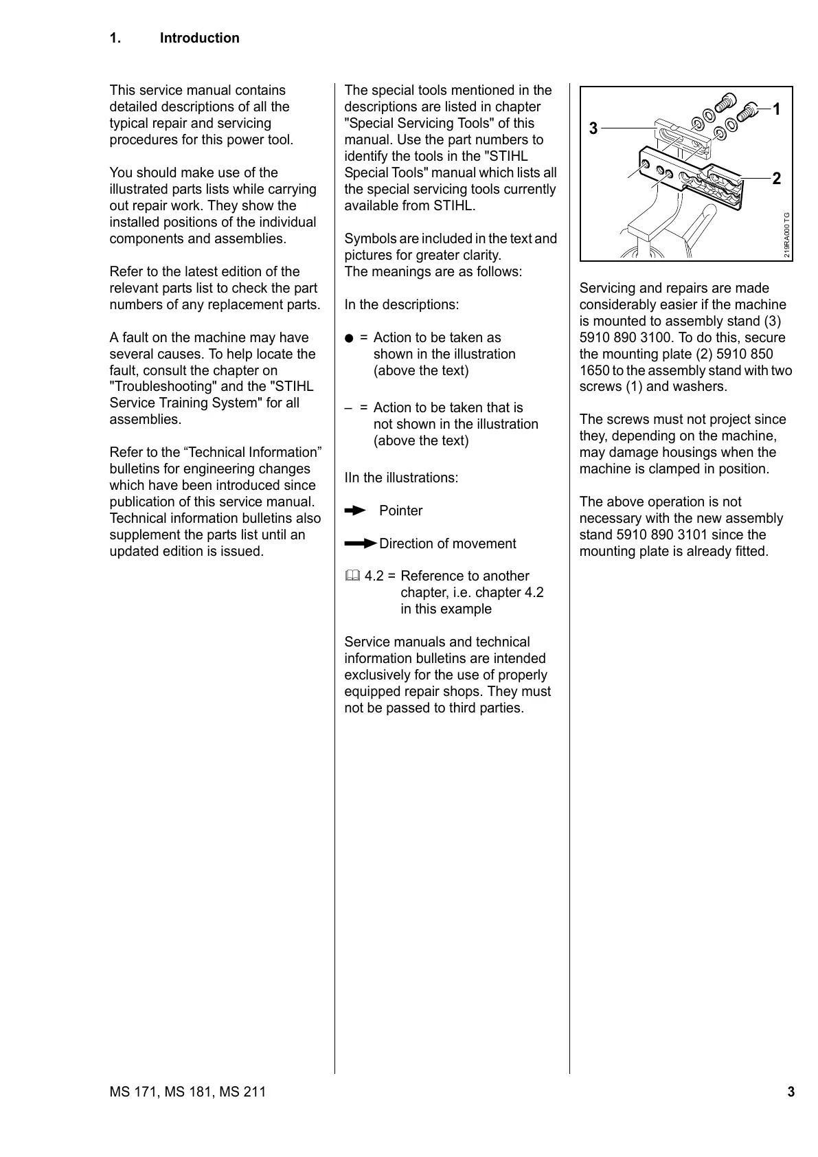
Servicing and repairs are made
considerably easier if the machine
is mounted to assembly stand (3)
5910 890 3100. To do this, secure
the mounting plate (2) 5910 850
1650 to the assembly stand with two
screws (1) and washers.
The screws must not project since
they, depending on the machine,
may damage housings when the
machine is clamped in position.
The above operation is not
necessary with the new assembly
stand 5910 890 3101 since the
mounting plate is already fitted.
1
2
3
219RA000 TG
 Loading...