ENSK
21
TRHUSRHRCSLVLTROELBGETAZKK
0478 111 9841 A - EN
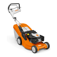
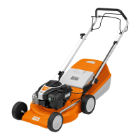
8.1 Adjusting the mono
handlebar (RM 448 PC,
RM 448 TC, RM 448 VC)
Folding down handlebar:
Transport position (for cleaning, for
space-saving transport and for storage of
the machine):
● Detach the recoil starter rope from the
rope guide. (Ö 7.5)
● Hold the upper handlebar (2) with one
hand at its highest point and lift (relieve
load) slightly.
● Press the detent lever (1) downwards
and hold.
● Fold down handlebar (2) forwards.
Working position (to push machine):
● Fold the handlebar (2) up rearwards
and ensure that the handlebar is fully
engaged.
● Attach the recoil starter rope at the rope
guide. (Ö 7.5)
Height adjustment:
The height of the mono handlebar can be
adjusted to 2 levels:
● Hold the upper handlebar (2) with one
hand at its highest point and lift (relieve
load) slightly.
● Press the detent lever (1) downwards
and hold.
● Move the handlebar (2) into the
required position.
● Release the detent lever (1) and ensure
that the handlebar is again fully
engaged.
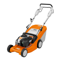
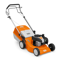
8.2 Folding down the dual
handlebar (RM 443, RM 443 T,
RM 448 PT, RM 448 T,
RM 448 TX)
Transport position (for cleaning, for
space-saving transport and for storage of
the machine):
● Detach the recoil starter rope from the
rope guide. (Ö 7.5)
● Open the quick-clamping devices (1) –
fold downwards – and fold down upper
handlebar (2) forwards.
Working position (to push machine):
● Fold up the upper handlebar (2)
rearwards and hold with one hand.
● Close quick-clamping devices (1) (fold
upwards).
● Attach the recoil starter rope at the rope
guide. (Ö 7.5)
8.3 Grass catcher box
Attaching:
● Open the discharge flap (1) and
hold it open.
● Attach the grass catcher box (2) to the
mountings (3) on the rear of machine by
means of the locating lugs.
● Close the discharge flap (1).
Detaching:
● Open the discharge flap (1) and hold it
open.
● Lift the grass catcher box (2) and
remove it rearwards.
● Close the discharge flap (1).
8.4 Central cutting height
adjustment
Six different cutting heights can be
set.
Level 1 = 25 mm
Level 6 = 75 mm
Setting the cutting height:
● Hold the handle (1), pull the lever (2)
upwards and hold.
● Set the required cutting height by
moving the machine upwards and
downwards. The current cutting height
can be read off at the cutting height
indicator (3) by means of the
marking (4).
8. Controls
Danger of pinching!
When actuating the detent lever,
always hold the upper handlebar
with one hand at its highest point.
Never place your fingers between
the handlebar and bracket (above
and below the detent lever).
8
Danger of pinching!
The upper handlebar can be folded
down by releasing the quick-
release caps. For this reason,
always hold the upper
handlebar (2) with one hand at its
highest point when you open the
quick-release caps.
9
10
11
 Loading...