13 - English
INSTALLATION
MAKING THE ELECTRICAL CONNECTIONS
WARNING:
Verify the power has been disconnected to both
the room and the wall switch before making the
electrical connections. Failure to do so could
cause fire, electric shock, serious personal injury,
or death.
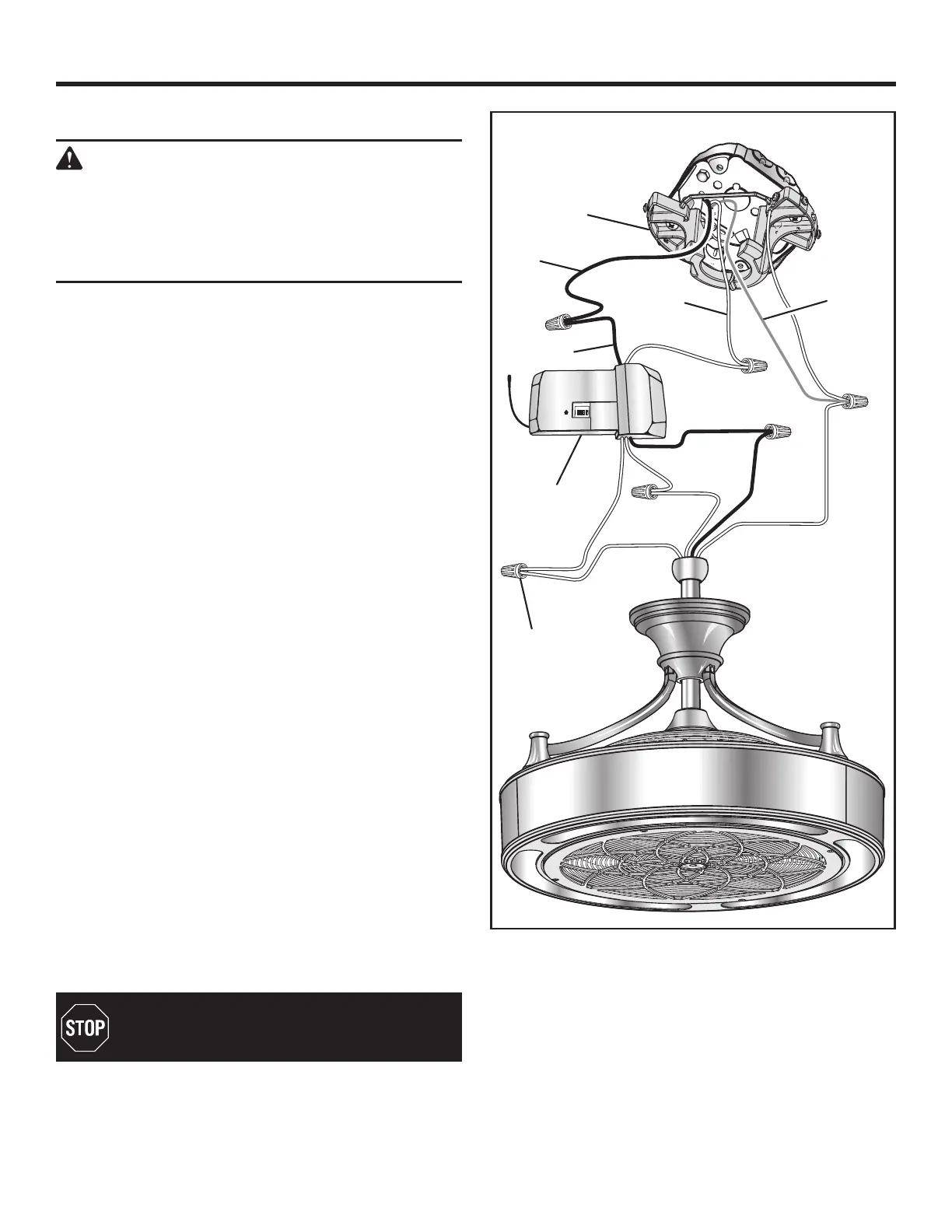
Connect the ceiling fan to the receiver:
Connect the ceiling fan black wire to the black wire on
the receiver marked TO MOTOR L.
Connect the ceiling fan white wire to the white wire on
the receiver marked TO MOTOR N.
Connect the ceiling fan blue wire to the blue wire on the
receiver marked FOR LIGHT.
Connect the receiver to the 120V electrical supply wires:
If your outlet box has a ground wire (green or bare cop-
per), connect it to the ground wire on the ceiling fan’s
pivot ball. If there is no ground wire in your outlet box,
connect the ground wire on the pivot ball to the ground
wire on the mounting bracket assembly.
Connect the white (neutral) supply wire to the white wire
on the receiver marked AC in N.
Connect the black (hot) supply wire to the black wire on
the receiver marked AC in L.
NOTE: If your electrical box has both red and black hot
wires, only one of these will be needed. Choose the sup-
ply wire that matches the wall switch you want to use for
your ceiling fan. Use a wire cap and electrical tape to seal
off the other wire and tuck it back up into the box and
out of the way.
Install a plastic wire nut over each connection to secure.
Reinforce with electrical tape as needed to make sure
no bare wire is visible at the wire nuts (except for a bare
ground wire, if present).
Spread the wires apart so the green and white wires go
to one side and the black and blue go to the other, then
carefully tuck all the wire connections up into the outlet
box.
NOTE: Orient the wires so the wire nuts are facing up
and are not touching each other. This will help minimize
potential noise once the installation is complete.
ON
ON
DIP
1 2
3
4
For Canada installations, refer to the Canada
Installation Addendum and connect the support
cable to the eye bolt or anchor assembly now.
MOUNTING
BRACKET
GROUND
CONDUCTOR
BLACK
BLACK
WHITE
GREEN
WHITE
BLACK
BLACK
WHITE
WHITE
GREEN
BLUE
BLUE
RECEIVER
WIRE
NUT