EasyManua.ls Logo

StoneL QUARTZ Series - User Manual

Default Icon
7 pages
Print Icon
To Next Page IconTo Next Page
Loading...
StoneL
26271 US Hwy 59
Fergus Falls, MN 56537
USA
Telephone: 218.739.5774
Toll Free: 800.843.7866
Fax: 218.739.5776
E-mail: sales@stonel.com
Website: www.stonel.com
© 2014 StoneL
with 4-20 mA Position Transmitter
or Potentiometer
(QX5O___, QN5O___, QXBO___, QNBO___, QX7O___, QN7O___, QXCO___, QNCO___)
Installation & Adjusting Instructions
QUARTZ®
SERIES
Pub # 105202revC
Thru-Bolt™ Mounting
1. Attach mounting plate to actuator using fasteners
and lockwashers provided.
2. Loosen indicator cover set-screw.
2a. Rotate indicator cover to desired viewing angle and
retighten set-screw. (Make sure indicator cover is
pushed all the way into housing slot.)
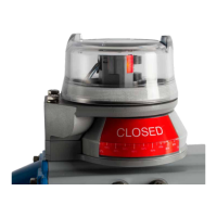
3. Rotate coupling spacer and indicator drum to
desired position. (OPEN or CLOSED appearing
through indicator window)
4. Remove spacer screw and fit torque coupling or
Namur coupling onto coupling spacer. Separate
spacer and indicator drum and rotate spacer to align
coupling with actuator shaft. Fit coupling spacer
over indicator drum drive hub.
4a. Secure torque coupling assembly or Namur coupling
with screw of proper length. (Additional coupling
spacers and longer screw may be required on some
mountings.)
5. Slide Thru-Bolts with washers into housing and fit
retaining quad-rings over bolts to retain them.
5a. Top of actuator shaft should be within 1/4"
(6.35mm) from coupling screw head or Namur
coupler.
5b. Torque coupler or Namur coupler must be fully
engaged in slot and be centered on the shaft or
block attached to the shaft.
6. Operate actuator to full open and full closed
positions and check for proper alignment between
switch and actuator. Eccentricity of shaft must
be no greater than .01" (.254mm) from
centerline. The torque coupler or Namur coupler
must be centered on the flats of the actuator shaft or
block in both the full open and full closed position.
Realign as necessary and final tighten Thru-Bolts.
7. "Fine-tune" visual indicator cover repeating #2 and
lightly tighten set screw.
Approval Agency Controlled Document.
No Changes Authorized Without Prior Agency Approval
CAUTION:
TO PREVENT IGNITION OF HAZARDOUS ATMOSPHERES,
REPLACE COVER BEFORE ENERGIZING THE ELECTRI-
CAL CIRCUITS.
KEEP COVER TIGHTLY CLOSED WHEN IN OPERATION.
NOTE:
FOR SIL APPLICATIONS REFERENCE THE QUARTZ
VALVE POSITION INDICATOR SAFETY MANUAL AVAIL-
ABLE AT: www.stonel.com/approvals.
Question and Answer IconNeed help?

Do you have a question about the StoneL QUARTZ Series and is the answer not in the manual?

Summary

Installation & Adjusting Instructions

Thru-Bolt Mounting Procedure

Step-by-step guide for installing the unit using the Thru-Bolt mounting system, covering attachment, alignment, and adjustments.

Safety Precautions

Crucial warnings for preventing ignition in hazardous atmospheres and ensuring operational safety by keeping covers closed.

Position Transmitter Calibration

Zero Position Setup

Connect an ohm meter to set the desired "zero" position for the potentiometer.

Span and Zero Adjustment

Adjust zero and span trimpots for 4mA and 20mA outputs respectively.

Hazardous Location Installation Diagram

Intrinsic Safety Installation Notes (Ex ia IIC T5;T6)

Special Conditions for Safe Use

Addresses electrostatic charge prevention and cleaning methods for enclosures in hazardous zones.

Potentiometer Calibration

Intrinsic Safety Hazardous Location Installation Diagram

Safety Warnings

Precautions regarding electrostatic discharge and cleaning methods for intrinsic safety.

StoneL QUARTZ Series Specifications

General IconGeneral
CategoryTransmitter
ManufacturerStoneL
SeriesQUARTZ Series
Communication ProtocolHART
Operating Temperature-40°C to 85°C (-40°F to 185°F)
Enclosure RatingIP66, NEMA 4X

Related product manuals