Do you have a question about the StoneL Quartz QX Series and is the answer not in the manual?
Describes the purpose and scope of the installation, maintenance, and operation manual.
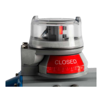
Explains the information found on the identification plate attached to the Quartz unit.
Details the Quartz's adherence to European Directives and its CE marking.
Provides guidance on the proper recycling and disposal of the Quartz unit.
Outlines critical safety measures to prevent damage and injury during operation.
Illustrates the various components of the Quartz unit for assembly reference.
Lists materials, unit weights, and dimensions for all Quartz valve monitor models.
Presents precise dimensional drawings for short and extended visual indicator options.
Diagram showing components for the extended visual indicator assembly.
Step-by-step guide for installing the Quartz with an extended visual indicator.
Diagram showing components for the short visual indicator assembly.
Step-by-step guide for installing the Quartz with a short visual indicator.
Details on who can perform maintenance and repair, and required parts.
Information on field wiring, code compliance, and installation precautions.
Introduction to various types of inductive proximity sensors used in Quartz units.
Specifications, wiring diagram, and Touch & Tune settings for SST sensors (33).
Specifications, wiring diagram, and Touch & Tune settings for SST sensors (35).
Specifications and wiring diagrams for SST solid state proximity sensors (X).
Detailed instructions for Touch & Tune switch setting for SST sensors (X).
Specifications and wiring diagrams for P+F 3-wire solid state sensors (E, F).
Detailed instructions for Touch & Tune switch setting for P+F sensors (E, F).
Introduction to intrinsically safe inductive proximity switches.
Specifications, wiring, and Touch & Tune settings for NAMUR sensors (44).
Specifications, wiring, and Touch & Tune settings for NAMUR sensors (45).
Specifications, wiring, and Touch & Tune settings for P+F NAMUR sensors (A).
Specifications, wiring, and Touch & Tune settings for P+F NAMUR sensors (N).
Introduction to different types of reed proximity switches.
Specifications and wiring diagrams for SPST Maxx-Guard sensors (L, P).
Specifications and wiring diagrams for SPDT Maxx-Guard sensors (G, H, S).
Specifications and wiring diagrams for intrinsically safe SPST Maxx-Guard sensors (J).
Specifications and wiring diagrams for intrinsically safe SPDT Maxx-Guard sensors (M).
Introduction to mechanical micro switches used in Quartz units.
Specifications for micro switches with silver and gold contacts.
Wiring diagrams for 4 and 6 SPDT mechanical micro switches.
Specifications and wiring diagram for DPDT mechanical micro switches.
Introduction to Valve Communication Terminals (VCT) functionalities.
Specifications and wiring for VCT with DeviceNet™ communication.
Details on the DeviceNet Wink feature and the Fault Bit functionality.
Specifications and wiring for VCT with Foundation Fieldbus communication.
Instructions for Touch & Tune switch setting for Foundation Fieldbus VCTs.
Specifications and wiring for VCT with AS-Interface communication.
Specifications and wiring for VCT with AS-Interface and extended addressing.
Introduction to position transmitters and potentiometers.
Specifications for 4-20mA transmitters with and without switches.
Wiring diagrams for 4-20mA position transmitters with various switch types.
Procedures for calibrating 4-20mA transmitters and Touch & Tune settings.
Specifications for potentiometers with SPDT, SPST, and solid state switches.
Wiring diagrams for potentiometers connected to various VCT types.
Procedures for calibrating potentiometers and Touch & Tune switch settings.
Introduction to Expeditor units and their operation sequences.
Describes fill control and emergency shutdown (ESD) operation sequences.
Details on Expeditors using mechanical switches with silver or gold contacts.
Details on Expeditors using Maxx-Guard proximity sensors.
Details on Expeditors with DeviceNet™ communication.
Details on Expeditors with Foundation Fieldbus communication.
Details on Expeditors with AS-Interface communication.
Defines the coding structure for QG series model and type designations.
Defines the coding structure for QN series model and type designations.
Defines the coding structure for QX series model and type designations.
Manufacturer's declaration of product conformity with standards and directives.
Details ATEX, IECEx, and other conditions for safe use and product marking.
Provides diagrams for intrinsic safety installation of Quartz units.
Notes and parameters for intrinsic safety installation under Ex ia IIC T6 conditions.
Installation diagrams for specific intrinsically safe sensor types.
Installation diagrams for intrinsically safe sensors of type QN*M and QX*M.
Installation diagrams for intrinsically safe sensors with specific model codes.
Installation diagrams for intrinsically safe sensors of type QN*N and QX*N.
Installation diagrams for intrinsically safe sensors of type QN*A and QX*A.
| Brand | StoneL |
|---|---|
| Model | Quartz QX Series |
| Category | Measuring Instruments |
| Language | English |