StoneL publication 105406revA
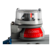
7 QZ 70 en Quartz | 49
7 Appendix
7.1 Controlled installation drawings
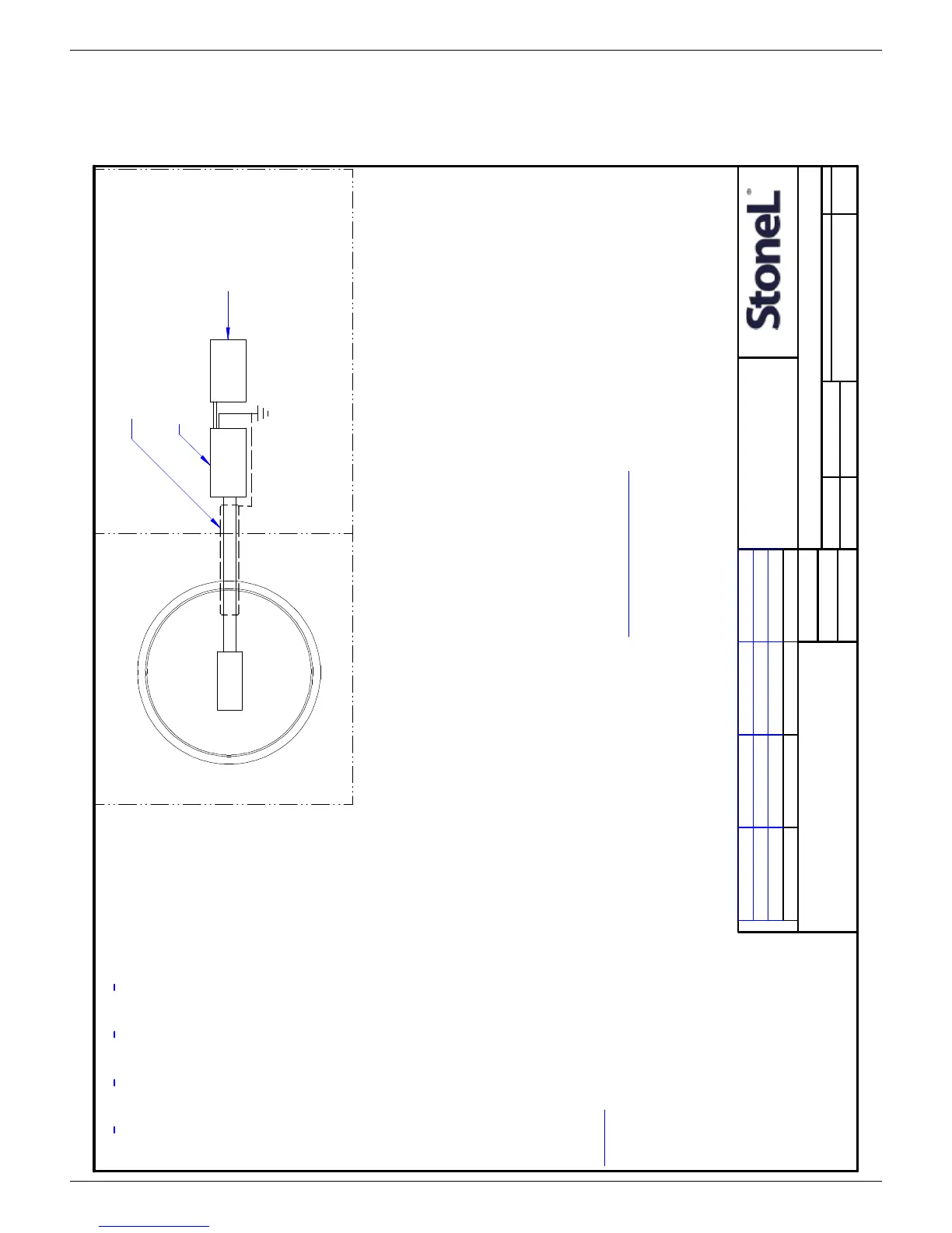
I.S. CONTROL, QUARTZ SERIES
NS
6/15/2007
SK
BL
RK
105193
SHEET
7
A
TOLERANCES (UNLESS OTHERWISE SPECIFIED):
X.XXX
`.005 ANGLES ` 0~ 30'
X.XX
`.010 FINISH f 125 RMS
X/X
`.015
D
1
SCALE
REV.DRAWING NO.
SIZE
TITLE
APPD.
CHK.
DR.
DATE
CONFIDENTIAL
THIS DRAWING AND ALL INFORMATION CONTAINED
HEREIN IS THE PROPERY OF AND IS SUBJECT TO
CHANGE BY STONEL. DRAWING IS NOT TO BE
REPRODUCED OR REVEALED TO ANY OTHER PARTY
UNLESS AUTHORIZED BY STONEL.
METSO AUTOMATION, FERGUS FALLS, MN U.S.A.
R
E
V
IS
IO
N
S
OF
REVISION ECO DATE BY
HAZARDOUS
(CLASSIFIED)
LOCATION
NON-HAZARDOUS
(SAFE AREA)
LOCATION
Intrinsically Safe
Ground
S
t
o
n
e
L
E
n
c
l
o
s
u
r
e
4-20mA
TRANSMITTER
(-)
(+)
INSTALLATION NOTES (Class I, II, III; Division 1; Groups A, B, C, D, E, F, G):
Entity Parameters: Vmax = 30 Vdc Imax = 100 mA Ci = 66 nF Li = 0.80 mH Pi = 2.0 W
1. Voc or Vt < Vmax, Isc or It < Imax, Ca > Ci + Ccable, La > Li + Lcable.
2. Dust-tight conduit seal must be used when installed in Class II and Class III environments.
3. Control equipment connected to barrier must not use or generate more than 250 Vrms or Vdc.
4. Installation should be in accordance with ANSI/ISA RPA12.6 "Installation of Intrinsically Safe Systems
for Hazardous (Classified) Locations" and the National Electrical Code (ANSI/NFPA 70).
5. The configuration of associated apparatus for each sensor wiring pair must be FMRC Approved.
6. Associated apparatus manufacturer's installation drawing must be followed when installing this
equipment.
7. To maintain intrinsic safety, wiring associated with each sensor must be run in separate cables or
separate shields connected to intrinsically safe (associated apparatus) ground.
8. Switches and/or transmitter are optional based on model number. (if more than 2 switches, follow
instructions above for each switch.)
9. Conduit Grounding - Upon installation verify electrical continuity between conduit and ground terminal.
10. Substitution of components may impair hazardous location safety.
WARNING:
1. When used in intrinsic safety applications, the metal enclosure shall be installed in such a manner as to
prevent the possibility of sparks resulting from friction or impact.
2. To prevent the risk of electrostatic sparking, the equipment enclosure shall be cleaned only with a damp
cloth.
INSTALLATION NOTES (Ex ia IIC T5/T6):
Entity Parameters: Ui = 30 Vdc; Ii = 100 mA; Ci = 66 nF; Li = 0.8 mH; Pi = 2.0 W
1. Voc or Vt < Ui, Isc or It < Ii, Ca > Ci + Ccable, La > Li + Lcable.
2. Dust-tight conduit seal must be used when installed in Zone 20, Zone 21, and Zone 22
environments or where Ingress Protection of IP67 is required.
3. Control equipment connected to barrier must not use or generate more than 250 Vrms or Vdc.
4. Installation should be in accordance with appropriate local code or practice.
5. The configuration of associated apparatus for each sensor wiring pair or solenoid wiring pair
must be approved.
6. Associated apparatus manufacturer's installation drawing must be followed when installing this
equipment.
7. To maintain intrinsic safety, wiring associated with each sensor or solenoid coil wiring must be
run in separate cables or separate shields connected to intrinsically safe (associated apparatus)
ground.
8. Conduit Grounding - Upon installation verify electrical continuity between conduit and ground
terminal.
9. Resistance between Intrinsic Safe Ground and earth ground must be less than one ohm.
10. Substitution of components may impair hazardous location safety.
Special Conditions for Safe Use:
1. Parts of the enclosure are non-conducting and may generate an ignition-capable level of
electrostatic charge under certain extreme conditions. The user should ensure that the equipment
is not installed in a location where it may be subjected to external conditions which might cause a
build up of electrostatic charge on non-conducting surfaces. Additionally, cleaning of the
equipment should be done only with a damp cloth.
2. When installed within a Zone 0 location, the metal enclosure shall be installed in such a manner
as to prevent the possibility of sparks resulting from friction or impact
.
Separate
Shields
Intrinsic Safety Barrier
(Associated Apparatus)
Control
Equipment
B 11/17/09 BB5457
C 04/20/15 BB106 37
D 12/29/15 RB11363
QN5*
, QX5*, QN7*, QX7*
NOTE:
1) IF * IS "J" OR "K", ALSO SEE SHEET 3.
2) IF * IS "M", ALSO SEE SHEET 4.
3) IF * IS "4" OR "R", ALSO SEE SHEET 5.
4) IF * IS "N", ALSO SEE SHEET 6.
5) IF * IS "A", ALSO SEE SHEET 7.
 Loading...