7 QZ 70 en34 | Quartz
StoneL publication 105406revA
4.6 Position transmitters and potentiometers
4.6.1 4 to 20 mA position transmitters with and without switches (Type 5_, 7_)
Applicable models
Standard potentiometer QN5_, QX5_
High performance potentiometer QN7_, QX7_
Specications
Output 2-wire 4-20 mA
Voltage range 10 - 40 VDC
Recommended voltage 24 VDC, 50 mA minimum
Maximum load 700 ohm @ 24 VDC (see load curve)
Span Adjustable from 35° to 270°
Maximum linearity error
Standard potentiometer (5) + 0.85°
High performance potentiometer (7) + 0.35°
Temperature range -40° to 80° C
Warranty Two years
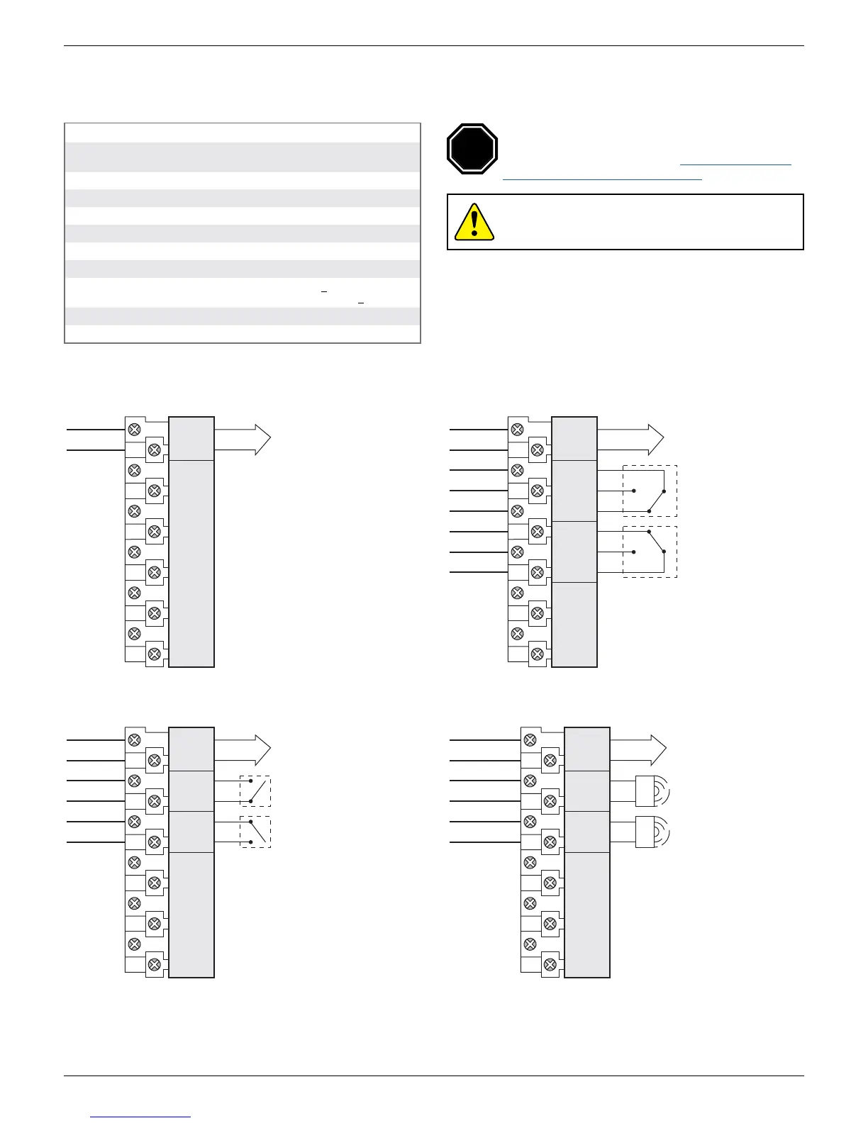
Wiring diagrams
Transmitter with SPST switches
Transmitter only Transmitter with SPDT switches
transmitter
top switch
bottom switch
TRANS +
TRANS -
TOP NO
TOP C
BTM C
BTM NO
SPARES
C
NO
1
2
3
4
5
6
TOP SW BTM SWTRANS
C
NO
-
+
transmitter
TRANS +
TRANS -
SPARES
3
4
5
6
7
8
9
10
TRANS
2
1
-
+
transmitter
top switch
bottom switch
TRANS +
TRANS -
TOP NC
TOP NO
TOP C
BTM C
BTM NO
BTM NC
SPARES
C
C
NO
NC
1
2
3
4
TOP SW BTM SWTRANS
NO
NC
-
+
Transmitter with solid state switches
transmitter
top switch
bottom switch
TRANS +
TRANS -
TOP NO/NC
TOP C
BTM NO/NC
BTM C
SPARES
NO
NC
C
1
2
3
4
5
6
TOP SW BTM SWTRANS
C
NO
NC
-
+
Caution: To prevent ignition of hazardous atmospheres,
replace cover before energizing the electrical circuits. Keep
cover tightly closed within operation.
Reference controlled installation drawing #105193 for
proper intrinsic safety installation details. Find document
in the Appendix on page49 or at www.stonel.com/en/
products/quartz/installation-manuals
STOP
 Loading...