7 QZ 70 en14 | Quartz
StoneL publication 105406revA
4.1 Inductive proximity sensors
4.1.4 P+F 3-wire solid state proximity sensors (E, F)
Applicable models
3- Wire NPN sinking sensor QN_E_, QX_E_
3- Wire PNP sinking sensor QN_F_, QX_F_
Specications
Conguration (2) 3-wire DC solid state sensors
Operation NO/NC (cam selectable)
Maximum current 100 mA
Voltage range 10-30 VDC
Maximum voltage drop <2.0 VDC
Current consumption <15 mA
Temperature range -40° to 80° C
Operating life Unlimited
Warranty Two years
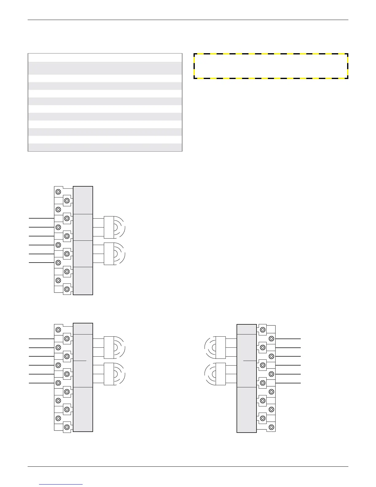
first switch fourth switch
third switchsecond switch
LOAD
1st SW -
1st SW +
2nd SW -
LOAD
2nd SW +
3rd SW -
LOAD
4th SW +
LOAD
4th SW -
3rd SW +
SPARES
SPARES
-
+
LOAD
1st SW
-
+
LOAD
1
2
TOP
3 5
4
4th SW3rd SW BTM
2nd SW
LOAD
+
-
LOAD
+
-
5
4
3
2
1
(4) 3-wire sensors (QN4E_, QN4F_, QX4E_, QX4F_)
bottom switch
top switch
TOP SW -
BTM SW -
BTM SW +
LOAD
LOAD
TOP SW +
SPARES SPARES
1
2
3
-
BTM SW
+
LOAD
LOAD
+
-
TOP SW
4 6
5
(2) 3-wire sensors (QN2E_, QN2F_, QX2E_, QX2F_)
Wiring diagrams
Bench test procedure
Connect a load resistor of 3K to 10K across a switch’s load and
(+) terminals (QN2E, QX2E), or a switch’s load and (-) terminals (QN2F,
QX2F). Using a 24 VDC power source, connect the power source
(+) lead to a switch’s (+) terminal and the power source (-) lead to
a switch’s (-) terminal. Connect a voltmeter across the load resistor.
Apply 24 VDC. With cam activation strip in front of sensor target, the
voltmeter will read >20 VDC. Activation strip away from sensor target
voltmeter will read 0 VDC.
WARNING
Failure to use a series load resistor when bench testing sensors
with a power supply will result in permanent damage to the unit.
 Loading...