StoneL publication 105406revA
7 QZ 70 en Quartz | 15
Touch & Tune switch setting
All adjustments assume you are looking down on the top of the
sensors. The edge of the cam metal strip will be at the edge of the
sensor target when activation occurs. When the cam is released be
sure it slides fully onto the spline. One spline tooth setting is 4 ½°.
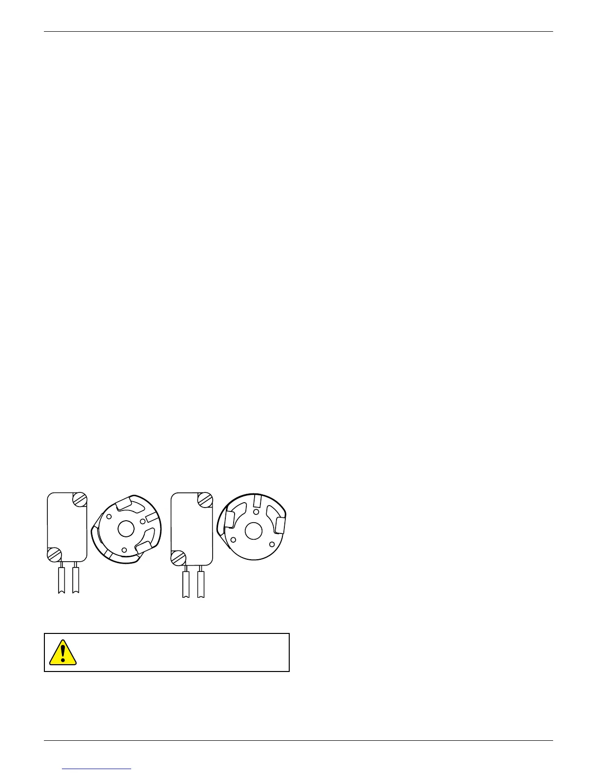
For normally open function (Fig. 1)
1. With the valve in the closed position and if the valve turns
counterclockwise to open, set both cams so that the metal
activation strips are 180° from each other with the bottom cam
set in the middle of the sensor target. Connect test equipment to
bottom switch as per Bench Test Procedure.
2. Lift the bottom cam and turn counterclockwise until the voltmeter
reads 0 VDC then clockwise again until the voltmeter just reads
>20 VDC. (Reverse the direction of the cam if the valve opens
clockwise.)
3. Move the valve to the opposite position (open), connect test
equipment to top switch. Push down on the top cam and rotate
counterclockwise until the voltmeter just reads >20 VDC. (Reverse
the direction of the cam if the valve opens clockwise.)
For the normally open operation, both sensors will be o during the
actuation period.
For normally closed function (Fig. 2)
1. With the valve in the closed position, set both cams so that the
metal activation strips are aligned with each other and set in the
middle of the sensor targets. Connect test equipment to bottom
switch as per Bench Test Procedure.
2. If the valve turns counterclockwise to open, pull up on the
bottom cam and rotate clockwise until the voltmeter just reads
0 VDC. (If the valve turns clockwise to open, rotate bottom cam
counterclockwise until the voltmeter reads 0 VDC)
3. Operate the valve to the opposite position (open). Connect test
equipment to top switch. Push down on the top cam. If the
voltmeter reads 0 VDC, rotate top cam clockwise until it reads >20
VDC. With the voltmeter reading >20 VDC rotate cam counter-
clockwise until the voltmeter just reads 0 VDC.
For the normally closed operation, both sensors will be activated
during the actuation period.
Fig. 1 cam set for
normally open sensor
function
Fig. 2 cam set for
normally closed
sensor function
Caution: To prevent ignition of hazardous atmospheres,
replace cover before energizing the electrical circuits. Keep
cover tightly closed within operation.
4.1.4 P+F 3-wire solid state proximity sensors (E, F) continued
 Loading...