7 QZ 70 en44 | Quartz
StoneL publication 105406revA
Applicable models
QN83_, QX83_
Specications
Electrical ratings 0.10 amp @ 125 VAC
Maximum voltage drop 3.5 volts @ 10 mA
6.5 volts @ 100 mA
Temperature range -40° to 80° C
Operating life 5 million cycles
Seal Hermetically sealed reed switch
Warranty Two years
Refer to Foundation Fieldbus module specifications and adjustment procedures on page30
4.7 Expeditors
4.7.5 With Foundation Fieldbus communication (83)
Caution:
To avoid damaging the module when
performing the position switch calibration procedure,
apply 9 - 32 VDC across FB + and FB -. Use the LEDs to
determine when switches are made. You cannot do this
procedure with an ohmmeter. No series load resistor
is required when attaching a 24 VDC power supply for
switch setting.
Caution: To prevent ignition of hazardous atmospheres,
replace cover before energizing the electrical circuits. Keep
cover tightly closed within operation.
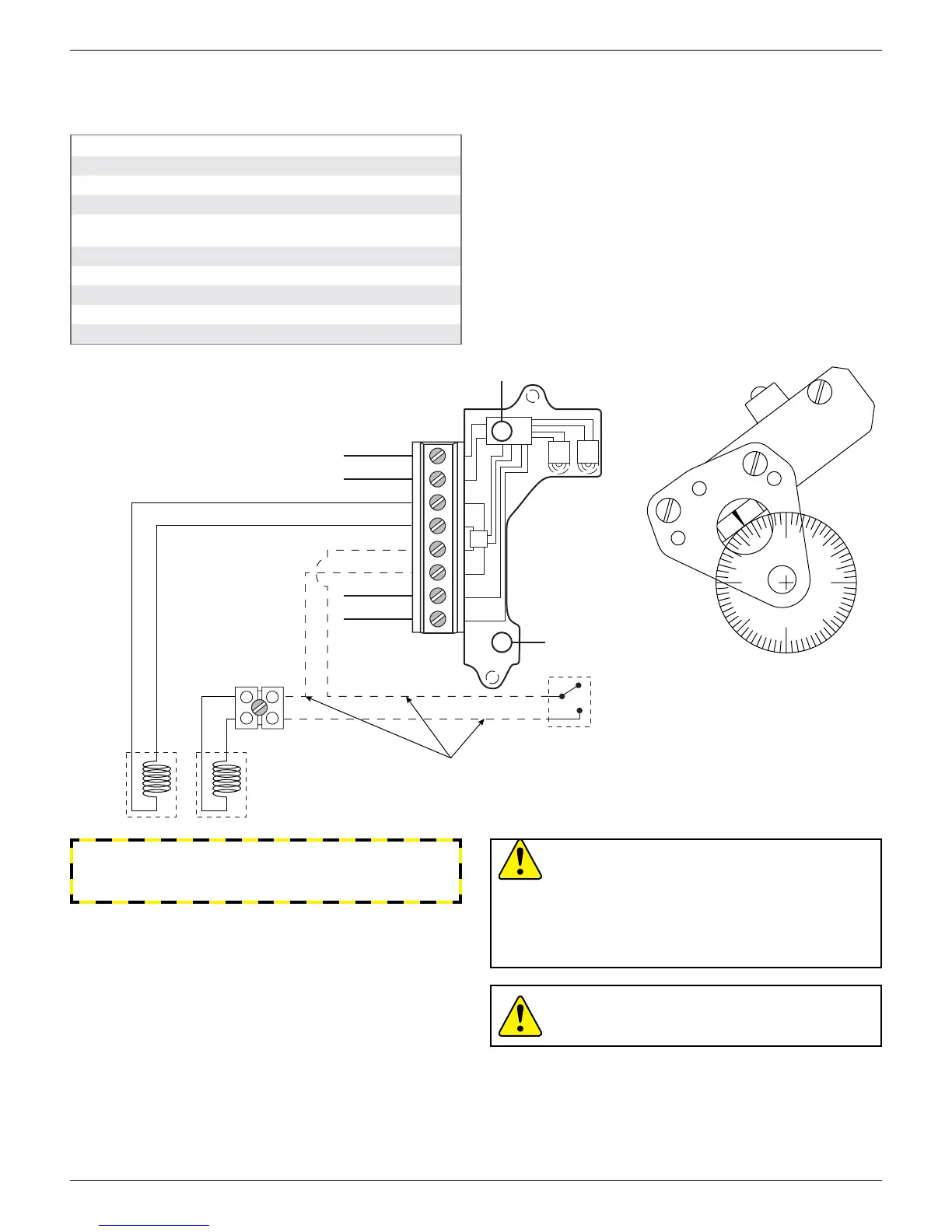
Intermediate switch setting
At full closed position lift top cam and rotate in clockwise direction
past 0° to desired degree setting for intermediate switch to be
energized. After setting is made, run actuator to full OPEN position.
De-energize primary solenoid and observe valve position after
intermediate switch is activated and secondary solenoid is energized.
Readjust top cam if necessary to increase or decrease angle of valve
when intermediate switch is activated.
Touch & Tune switch setting
All adjustments assume you are looking down on the top of the
sensors. The edge of the cam metal strip will be at the edge of the
sensor target when activation occurs. When the cam is released be
sure it slides fully onto the spline. One spline tooth setting is 4 ½°.
1. At full open position depress middle cam and rotate until sensor
is activated. (White highlights will overlap and green LED will light
if power is applied.) Release cam and be sure it slides fully onto
spline.
2. At full closed position lift bottom cam and rotate until sensor is
activated. (White highlights will overlap and red LED will light
if power is applied.) Release cam and be sure it slides fully onto
spline.
WARNING
Do not apply power to external power to output terminals as
this will damage the module.
Wiring diagram
180°
90°
1
5
°
7
5
°
3
0
°
45°
6
0
°
90°
0°
6
0
°
7
5
°
3
0
°
4
5°
1
5
°
Intermediate switch
LED
LED
*Solenoids not
supplied with unit
Primary
solenoid*
Secondary
solenoid*
Factory wiring
Intermediate
switch (top cam)
LED
LED
FB +
FB -
OUT1 +
OUT1 -
OUT2 +
OUT2 -
SIM JMPR
SIM JMPR
 Loading...