Do you have a question about the Storz THERMOFLATOR and is the answer not in the manual?
Illustrations of internal components and their layout for identification and assembly.
Comprehensive list of replacement parts with associated order numbers for maintenance.
Detailed explanation of the device's operating modes (initializing, intermittent, semi-continuous).
High-level overview of the device's functional components and their interconnections.
Detailed electrical schematics illustrating component connections and signal flow.
Overview of the control board's function, block diagram, and circuit diagram.
Information on part compatibility, required tools, and safety precautions for replacements.
Step-by-step instructions for accessing internal components by opening the device.
Procedures for replacing control, controller, and display boards, and the front panel.
Instructions for replacing the pressure manifold, power supply unit, and gas preheater.
Steps for replacing the EPROM and microcontroller, including essential precautions.
Notes on performing tests, required instruments, and initial setup for calibration.
Detailed steps for adjusting voltage, offsets, amplification, and heating element.
Procedures for testing the low-pressure safety valve and various operational functions.
Explains monitoring of pressure, temperature, and flow with associated alarms.
A guide for visual inspection and operational tests to ensure device safety.
Recommendations for regular maintenance, servicing, repair, and fuse replacement.
Procedures for installing the SCB module, including hardware and software aspects.
Steps to adjust serial numbers for multiple identical devices in the SCB network.
Details on software versions and their specific functional changes or improvements.
A template for recording results of safety checks, including electrical and operational parameters.
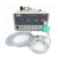
| Type | Insufflator |
|---|---|
| Manufacturer | Karl Storz |
| Gas | CO2 |
| Pressure Range | 0 - 30 mmHg |
| Heating Capability | Yes |
| Display | Digital |
| Power Supply | 100-240 V, 50/60 Hz |