Strasbaugh Machine Description
Version 4.0 - February 1998 2 - 13
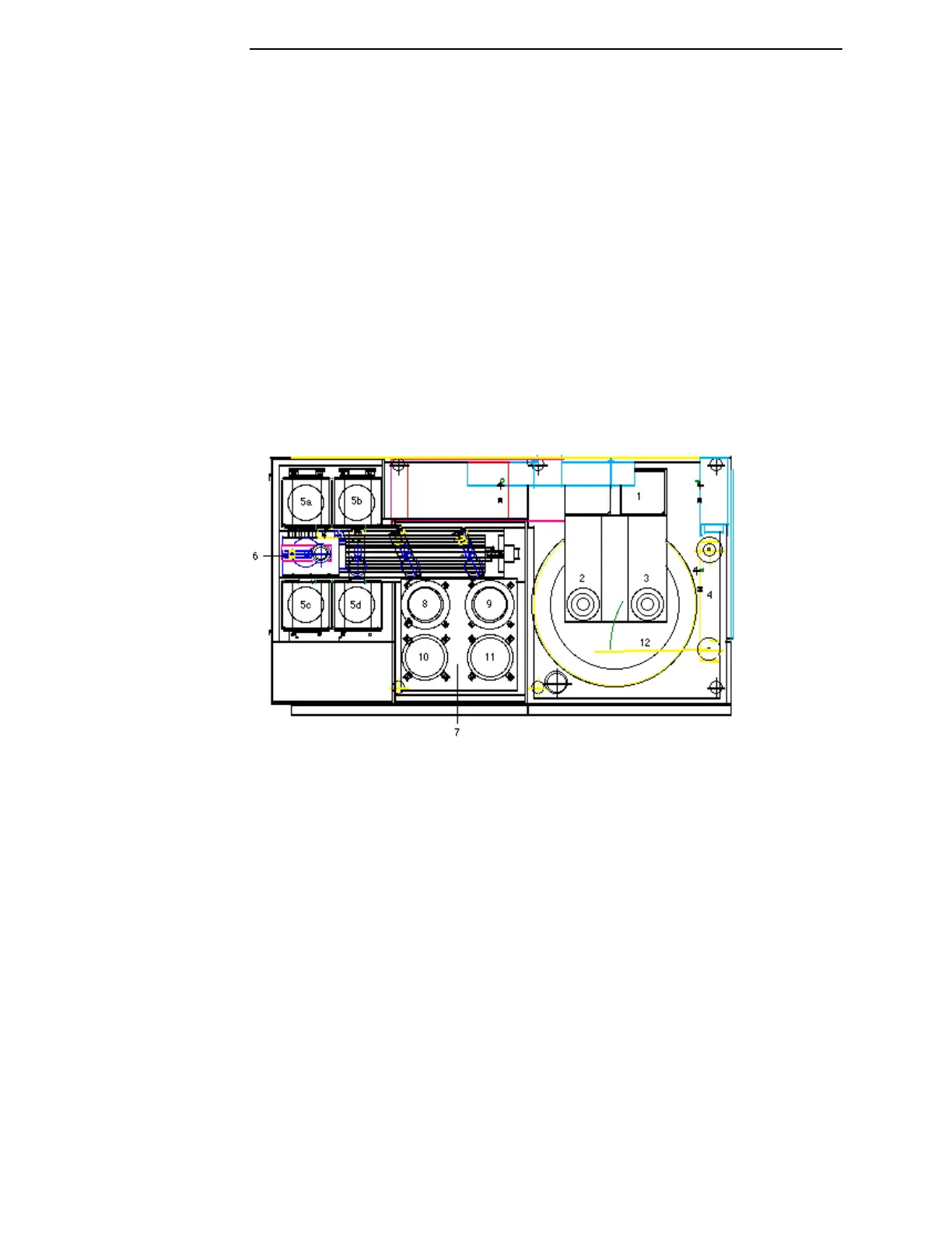
PLANARIZER SUBASSEMBLIES
Figure 2-5, shown below, is a top view of the standard Model 6DS-SP
Planarizer. (Refer to engineering drawing 217946U2.) The labeled
subassemblies participate in the wafer polishing process and manipulation of
the wafers.
For a top view of the machine with a second polish table installed, refer to
engineering drawing 225220U2.
Figure 2-5 Planarizer Subassemblies
1 Bridge Assembly 6 Robot Assembly
2 Left Spindle 7 Shuttle Assembly
3 Right Spindle 8 Left Load/Unload Station
4 Pad Conditioning Device Assembly 9 Right Load/Unload Station
5a Left Send Elevator Assembly 10 Left Carrier/Wafer Cleaning Station
5b Right Send Elevator Assembly 11 Right Carrier/Wafer Cleaning Station
5c Left Receive Elevator Assembly 12 Polish Table
*5d Right Receive Elevator Assembly
* or scrubber assembly