EasyManua.ls Logo

Stratus SAE-MS9000X - User Manual

Stratus SAE-MS9000X
23 pages
Print Icon
To Next Page IconTo Next Page
Loading...
Model No. SAE-MS9000X
Mid Rise Scissor Lift
Automatic Release
Lifting Capacity 9000 lbs
Installation & Operation &
Maintenance Instructions
Important Note
1. This equipment can not be installed, operated or repaired without reading instructions.
2. Electricity must be hooked up by certified electrician.
3. Do not use this equipment beyond its rated capacity.

Questions and Answers

Summary

Important Safety Instructions

Important Notices

General warranty, liability, and usage guidelines for the lift.

Qualified Personnel

Specifies requirements for personnel operating or servicing the lift.

Danger Notices

Lists critical safety warnings and precautions during operation and maintenance.

Safety Warnings and Labels

Visual and textual explanations of safety labels and warnings for safe operation.

Sound Level

Specifies the maximum allowable sound level for the lift.

Training Requirements

Emphasizes the need for professional training for lift operators.

Initial Operation Reminder

Instructions for initial lift operation, including air bleeding and speed adjustment.

Overview of the Lift

General Descriptions

Describes the electro-hydraulic system and safety features of the lift.

Technical Data

Provides key specifications such as model, capacity, lifting time, height, and power.

Construction of the Lift

Illustrates the main components and layout of the scissor lift.

Installation Instructions

Preparations Before Installation

Details necessary tools and equipment for installation.

Parts Checking and Packing List

Instructions for verifying all parts are present using the packing list.

Ground Conditions for Installation

Specifies requirements for the installation surface, including strength and flatness.

Precautions for Installation

Key precautions to follow during the installation process to ensure safety and proper function.

Installation Steps

Step-by-step guide for assembling and connecting the lift components.

Post-Installation Checks

Checklist to ensure all installation steps are completed correctly before operation.

Operation Instructions

Operational Precautions

Essential safety precautions to observe before and during lift operation.

Control Box Description

Identifies and explains the function of buttons and indicators on the control panel.

Operation Flow Chart

Visual representation of the lifting and lowering sequences.

Raising and Lowering the Lift

Detailed steps for raising and lowering the vehicle safely.

Emergency Lowering Procedure

Procedures for safely lowering the lift when power is unavailable.

Trouble Shooting

Maintenance

Parts Requiring Lubrication

Lists parts that require regular lubrication for optimal performance.

Daily Checking Items Before Operation

Daily inspection checklist to ensure the lift is safe for use.

Weekly Checking Items

Recommended checks to perform on a weekly basis for preventative maintenance.

Monthly Checking Items

Monthly maintenance tasks to ensure continued reliability of the lift.

Yearly Checking Items

Annual maintenance procedures for thorough inspection and servicing.

Annex

Annex 1. Packing List of the Whole Lift

Itemized list of all components included in the lift package.

Annex 2. Overall Diagram

Visual representation of the lift with key dimensions.

Annex 3. Diagram for Pneumatic System

Schematic illustrating the pneumatic control system for specific versions.

Annex 4. Hydraulic Working System

Diagram detailing the hydraulic components and their connections.

Annex 5. Wiring Diagram

Electrical schematic showing the wiring layout for the lift's control system.

Inside Layout of Control Box

Diagram showing the internal arrangement of components within the electrical control box.

Annex 6. Separate Diagrams for the Lift

Exploded views and part lists for the pump assembly and the main lift structure.

Spare Parts List - Electrical System

List of replacement electrical components with specifications and images.

Spare Parts List - Machine Part

List of replacement mechanical and hydraulic components.

Annex 8. Size and Weight Requirements on Vehicles

Table detailing vehicle dimensions and weight capacities for safe lifting.

Overview

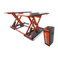
This document describes the STRATUS Mid Rise Scissor Lift, Model No. SAE-MS9000X, an electro-hydraulic lifting system designed primarily for tire service and other quick service tasks on vehicles.

Function Description

The lift operates by an electro-hydraulic system where a gear pump delivers hydraulic oil to oil cylinders, pushing their pistons upwards to raise the platforms. It is designed to lift the entire body of vehicles, with its maximum weight within the specified lifting capacity. The lift incorporates two safety solutions: an anti-surge valve in the hydraulic system to prevent sudden platform drop in case of a broken oil hose, and an additional pneumatic safety lock.

Important Technical Specifications

  • Model No.: SAE-MS9000X
  • Lifting Capacity: 9000 lbs
  • Lifting Time: 40 seconds
  • Lifting Height: 39.37 inches
  • Power Supply: 110V/220V, Single Phase
  • Ground Conditions for Installation: Requires a smooth and solid concrete ground with a strength of more than 3000psi, flatness tolerance less than 5mm, and a minimum thickness of 200mm. Newly built concrete ground must undergo more than 28 days of cure and reinforcement.
  • Sound Level: The sound emitted from the lift should not exceed 75DB.

Usage Features

  • Operation: The lift is controlled via a control box with "UP" and "DOWN" buttons and an "Emergency Stop" button. To raise the lift, the user places four rubber pads under the vehicle's prop-points, ensuring the car's gravity is centered on the pads. The "UP" button is pressed until the pads touch the prop-points, then pressed again to lift the vehicle slightly higher for a final safety check. Once the desired height is reached, the "Emergency Stop" button is pressed before maintenance or repair work.
  • Lowering: To lower the lift, the "emergency stop button" is switched on (power indicator on), then the "DOWN" button is pressed. For models with a pneumatic safety lock, the platforms will first rise about 5cm to release the safety lock before descending.
  • Emergency Lowering (No Power):
    • Safety lock not engaged: The safety teeth on both sides must be tied up with rope and pulled upward to unlock them. Then, the core of the electro-magnetic valve on the pump assembly is manually loosened.
    • Safety lock engaged: The fitting opposite the oil outlet is screwed off to connect an optional hand pump. The hydraulic assembly is connected to the hand pump, and the pump handle is pressed down to raise the platforms and unlock the safety teeth. The safety teeth are then tied up with rope and pulled up. Finally, a wrench is used to loosen the core of the electro-magnetic valve to lower the platforms.
  • Hydraulic Oil Flow Valve Adjustment: This valve controls the lowering speed. Clockwise adjustment makes the down speed faster, while counterclockwise adjustment makes it slower. It's crucial to adjust this carefully, as excessive rotation can cause the vehicle to fall rapidly. The manual recommends adjusting by 1/8 or 1/16 scale.
  • Pressure Valve Adjustment: Clockwise adjustment increases pressure for more power, and counterclockwise adjustment decreases pressure for less power.
  • Dump Valve: In case of power failure or scissor lift malfunction, the safety lock must be manually released first. Then, the Dump Valve is pressed and adjusted clockwise to lower the lift. After the lift is down, the Dump Valve is pressed and adjusted counterclockwise to recover.
  • First-time Use (Air Bleeding): Before lifting a vehicle for the first time, the lift should be raised to its highest point and lowered to its lowest point 2-3 times repeatedly without any load. This process bleeds air from the hydraulic hose and cylinders, ensuring smooth operation.
  • First-time Use with Load: After air bleeding, the screw cap of the Hydraulic Oil Flow Valve should be loosened, and the middle hexagonal screw tightened clockwise. The "UP" button is used to raise the lift with a loaded vehicle. Then, the "DOWN" button is pressed and held to disengage the safety lock, and the Hydraulic Oil Flow Valve (middle hexagonal screw) is finely adjusted counterclockwise to achieve a lowering speed of 0.5 inch/sec or slower.
  • Safety Warnings: Numerous safety warnings are provided, including not installing on asphalt, reading all warnings before operation, not leaving controls while in motion, keeping hands and feet clear of moving parts, using only trained personnel, not wearing unfit clothing, keeping the work area tidy, ensuring safety locks are engaged, not rocking the vehicle, and regularly checking for proper synchronization and agility of moving parts.

Maintenance Features

Routine maintenance is crucial for safe and normal operation. The frequency of maintenance can be adjusted based on the lift's working conditions.

  • Parts to be Lubricated: Small idler wheel, rotor shaft, U-shape block, safety shaft, rotor shaft of oil tank, and slider.
  • Daily Checking Items (before operation):
    • Verify the safety lock system is engaged by sound.
    • Check if oil hoses are well connected and free of leaks.
    • Inspect the electrical system.
    • Ensure plug bolts are firmly screwed.
    • Check if safety teeth and safety block are matched correctly.
  • Weekly Checking Items:
    • Check the flexibility of moving parts.
    • Check the working conditions of safety parts.
    • Check the amount of oil in the oil tank (enough if platforms can be raised to highest position).
    • Ensure plug bolts are firmly screwed.
  • Monthly Checking Items:
    • Check if plug bolts are firmly screwed.
    • Check the tightness of the hydraulic system and screw firm any leaking joints.
  • Yearly Checking Items:
    • Empty the oil tank and check the quality of hydraulic oil.
    • Wash and clean the oil filter.
  • Long-term Storage: If the lift is unused for a long time, users should disconnect the power source, empty the oil tank, and lubricate moving parts with hydraulic oil. Disused oil must be disposed of properly for environmental protection.
  • Troubleshooting Guide: A comprehensive troubleshooting table is provided, listing common problems (e.g., motor not running, platforms lowering slowly), their potential causes (e.g., loose wire connection, damaged pump, low oil level), and corresponding solutions (e.g., check connection, replace part, add oil). Users are advised to contact dealers for help if issues cannot be resolved independently.

Stratus SAE-MS9000X Specifications

General IconGeneral
BrandStratus
ModelSAE-MS9000X
CategoryScissor Lifts
LanguageEnglish