10 MA_560_A4_180619_en
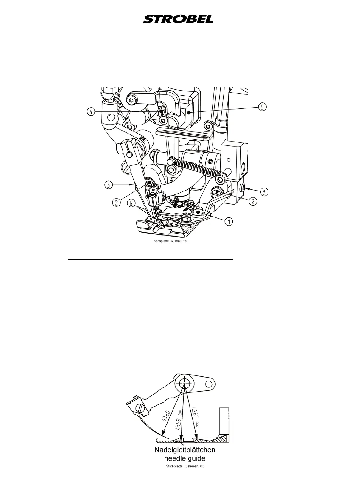
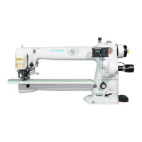
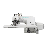
Fig. 1
3.1.3
The theoretic needle radius of 43.6 mm should be by 0.01 - 0.04 mm smaller at
the needle glide plate; i.e. a checked needle is lifted by
0.01 - 0.04 mm. Control by means of a dial gauge.
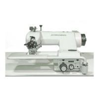
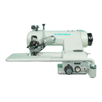
Setting the needle plate (Fig. 1 and Fig. 2)
If this setting is correct, there should be a distance of 0.03 - 0.06 mm between
needle and needle plate radius.
By loosening threaded pins (3) on the left and right hand side of the head and
by loosening fastening screws (2) the needle plate can be pushed carefully
upwards or downwards towards the needle.
Attention! Make sure that the needle plate is in horizontal position when
tightening the screws.
Fig. 2