259.10.57en
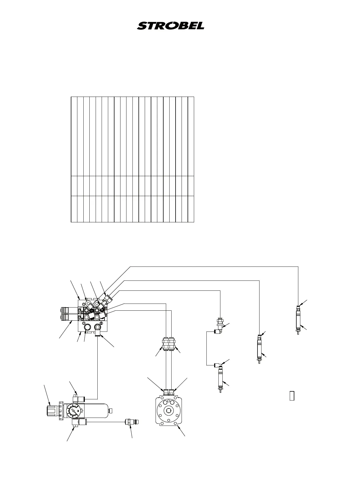
Pneumatic construction circuit diagram cl. 560 from version 4
3
r
1
p
B
A
3
r
p
1V1
1V2
(293.0841)
293.0857
298.0678
193.0473 2600 PA hose Ø6
193.0478 3000 PA hose Ø8
196.0716 3200 PA hose Ø4
293.0469 1 silencer R1/8
293.0772 2 lock screw R1/8
293.0837 2 L-threaded connection R1/8-4
293.0838 1 Y-plug connection 4
293.0850 3 L-threaded connection R1/8-6
293.0852 2 threaded connection R1/8-6
293.0853 1 L-threaded connection M5-4
293.0857 2 threaded connection M5-4
293.0975 1 service unit
293.0976 2 bulkhead union 6
293.0980 1 L-bulkhead union 4
297.0170 1 coupling Ø8
298.0211 3 miniature cylinder Ø8x12,5
298.0510 2 4/2-solenoid-way valve R1/8
298.0511 1 input module G1/8 left
298.0512 1 input module G1/8 right
298.0678 1 swivel drive
293.0975
297.0170
(293.0850)
193.0478
Ø
8 3000 lg
293.08503x
298.0512
293.07722x
298.0510 2x
298.0511
293.0469
293.08372x
293.0838
193.0473 Ø6
193.0473 Ø6 150 lg
193.0473 Ø6 150 lg
293.0852
293.0852
293.0976
293.0976
293.0853
298.0211
293.0980
196.0716 Ø4 430 lg
293.0857
298.0211
298.0211
193.0473 Ø6
193.0473 Ø6
196.0716 Ø4
196.0716 Ø4
196.0716 Ø4
B
A
4
service unit
solenoid valve
lifting
thread wiper
thread tension
supplementary thread tension
195.0536