14
TECHNICAL PASSPORT INSTALLATION AND MAINTENANCE INSTRUCTIONS
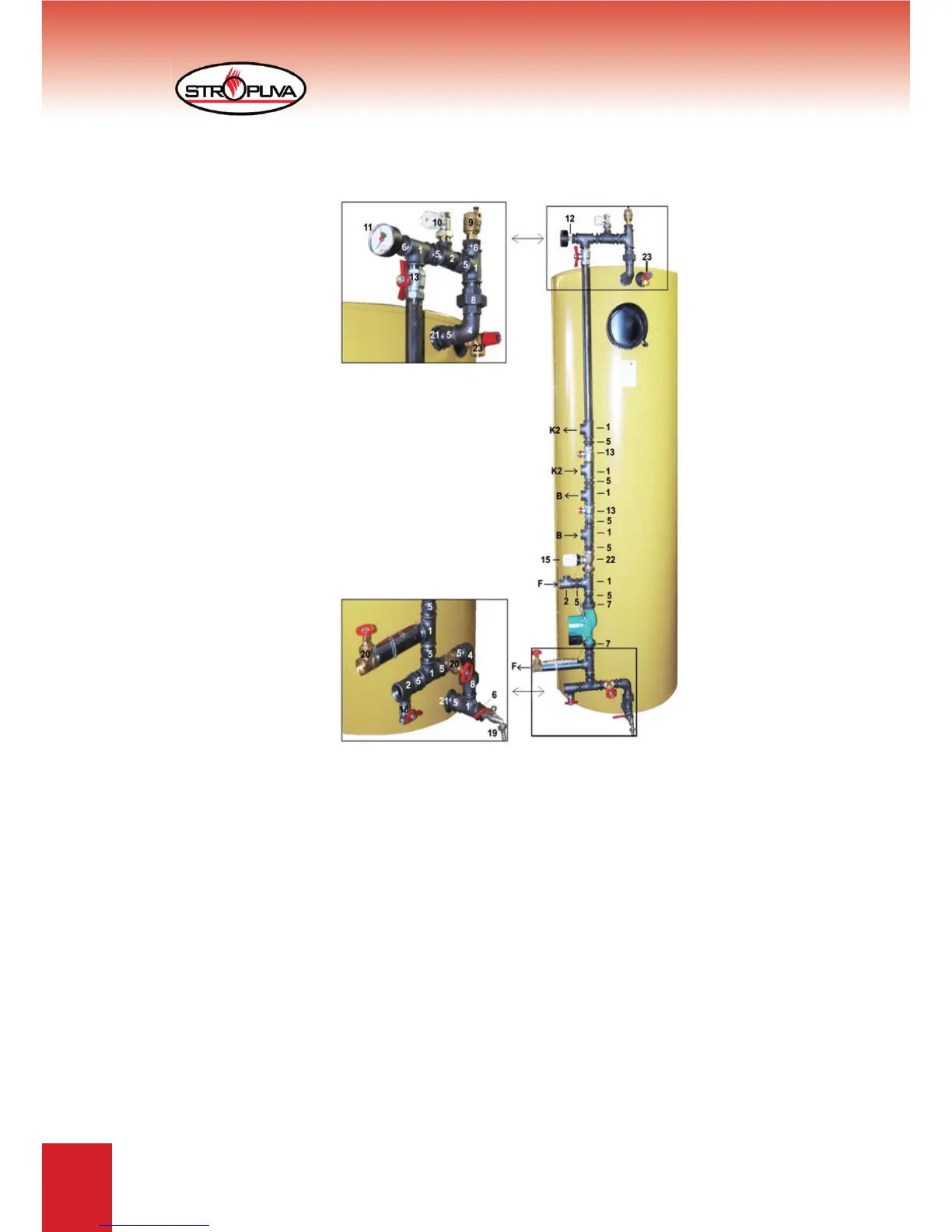
6.2 diagram of connecting ,,Stropuva” boiler to other boiler,
water heater and fl oor heating
1. Triple D25
2. Triple D25 x D15
4. Elbow D25 V/i
5. Nipple D25
6. Adapter D25 x D15
7. Circulation pump installation kit D25
8. Separable connection D25 V/i
9. Automatic bleeding device
10. Balance valve D25 V/i
11. Horizontal monometer 1/4“
12. Adapter D15 x 1/4“
13. Ball valve V/i 1“
14. Circulation pump
15. Thermostat head 20 - 50
0
C
1 8 . V a l v e f o r fi l l i n g u p i / i 1 / 2 “
- 10 pcs.
- 3 pcs.
- 2 pcs.
- 15 pcs.
- 3 pcs.
- 1 pcs.
- 2 pcs.
- 1 pcs.
- 1 pcs.
- 1 pcs.
- 1 pcs.
- 3 pcs.
- 1 pcs.
- 1 pcs.
- 1 pcs.
19. Valve for release 1/2
20. Disc valve made from brass V/V 1“
21. Adapter D32 x D25
22. Valve thermostat
23. Valve 1,5 bar
- 1 pcs.
- 2 pcs.
- 2 pcs.
- 1 pcs.
- 1 pcs.
F - to/out of fl oor heating
B - to/out of water tank
K2 - to/out of other boilers
For boilers S7, S10, S20, S7 BIO, S20 BIO and S10U, S20U, nodes are assembled from parts
D 20. For boilers S40, S40 BIO and S40U node is assembled from parts D25.
Figure 9