16
TECHNICAL PASSPORT INSTALLATION AND MAINTENANCE INSTRUCTIONS
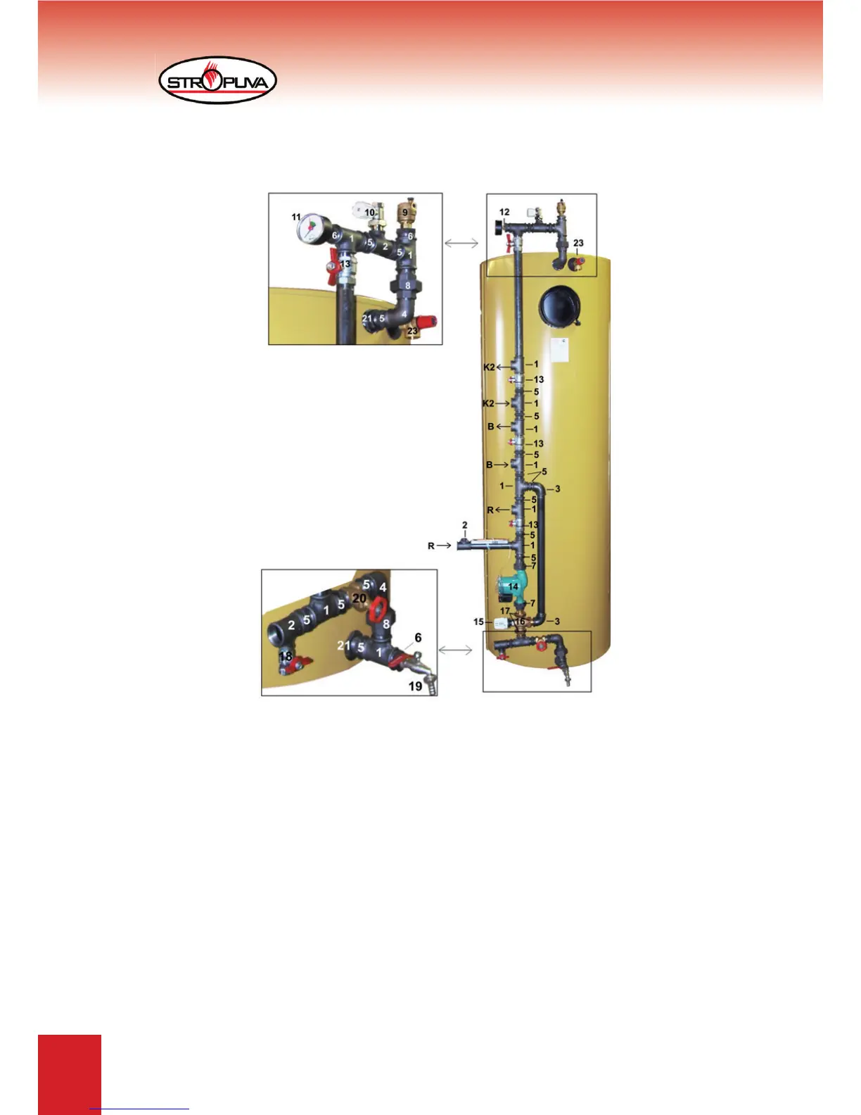
6.4 diagram of connecting ,,Stropuva” boiler to other boiler,
water heater, radiators
1. Triple D25
2. Triple D25 x D15
3. Elbow D25 V/V
4. Elbow D25 V/i
5. Nipple D25
6. Adapter D25 x D15
7. Circulation pump installation kit D25
8. Separable connection D25 V/i
9. Automatic bleeding device
10. Balance valve D25 V/i
11. Horizontal monometer 1/4“
12. Adapter D15 x 1/4“
13. Ball valve V/i 1“
14. Circulation pump
15. Thermostat head 20 - 50
0
C
16. Valve three directional for fl ow distribution
17. Threaded tip DN2 25
18. Valve for fi lling i/i 1/2“
19. Valve for release 1/2
20. Disc valve made from brass V/V 1“
21. Adapter D32 x D25
23. Valve 1,5 bar
- 11 pcs.
- 3 pcs.
- 2 pcs.
- 2 pcs.
- 15 pcs.
- 3 pcs.
- 1 pcs.
- 2 pcs.
- 1 pcs.
- 1 pcs.
- 1 pcs.
- 1 pcs.
- 4 pcs.
- 1 pcs.
- 1 pcs.
- 1 pcs.
- 3 pcs.
- 1 pcs.
- 1 pcs.
- 1 pcs.
- 2 pcs.
- 1 pcs.
B - to/out of water tank
K2 - to/out of other boilers
R - to/out of radiator
For boilers S7, S10, S20, S7 BIO, S10 BIO, S20 BIO and S10U, S20U, nodes are assembled
from parts D20. For boilers S40, S40 BIO and S40U node is assembled from parts D25.
Figure 11