Mon:
2.
The variable Mon control (talk back) is used to monitor your own
voice.This can be used to compare different microphones. To increase
the volume of the talk back rotate the control clockwise. To decrease
rotate counterclockwise. To turn off the talk back rotate the control
completely counterclockwise.
Transmit Power or PWR
3.
- This variable control allows you to adjust
your power output.
Band Selector:
4.
This switch allows you to switch bands, each
band contains 40 channels, with each channel being on a different
frequency.
Dimmer Switch:
5.
This switch controls the brightness for the front
panel. To adjust the brightness move this switch to the left “DIM”
setting and then rotate the channel selector clockwise for more light or
counter-clockwise for less.
HIC:
6.
This is the Hi-Cit Filter, once this function is enabled, the radio
will cut out high frequency interference. Use is dependent on reception
conditions.
RB:
7.
This switch controls the "roger beep" circuitry. Simply put the
roger beep is a tone that sounds when a radio operator un-keys their
microphone. When the switch is on the RB position the roger beep is
turned on. When moved the switch is moved to the middle position it is
switched off.
PRG:
8.
This switch allows you to select which roger beep is will be
activated when the RB switch is on. It also allows you select if you’d
like the auto squelch activated and lets you add specic channels to
scanned when the scan feature is activated. See section “PRG Menu”
for more details on this function.
+10Khz-:
9.
This switch will add 10 Khz to your current operating
frequency.
RX / TX:
10.
The TX symbol will appear when the radio is receiving and
the TX symbol will appear when the radio is transmitting.
Channel Display:
11.
The channel display indicates the currently
selected channel.
VFO:
12.
The VFO switch allows you to move through the radios entire
frequency range without changing bands. To use VFO mode move
this switch all the way to the right position. For Band operation this
switch should be in the middle position.
Scan / CH9 / CH19:
13.
Pressing this button once when the radio is in
band mode will automatically take you to CH9 of which ever band
you are currently on. Pressing it a second time will bring you to CH19
on your current band. To scan channels in band mode you must rst
press and release the FUNC button and then press the Scan button,
the radio will then start to scan. In VFO mode this button will only
enable scanning, therefore it’s notnecessary to rst press the FUNC
button.
Color:
14.
Pressing this button changes the color of the front panel and
display. Each time it’s pressed it will change to a new color. Pressing
this button allows you to select the color loop mode where the radio
will automatically cycle through all of the colors.
Mode:
15.
This switch controls what mode of operation the radio is in,
option are AM, FM & PA.
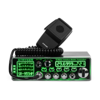
Microphone Input:
16.
The Stryker SR655 accepts microphones with a
female 4 pin connector. For further wiring information please see the
next page of this manual. Our SR-65BC is an excellent choice if you
need noise canceling microphone. Please see our website for further
details.
On/Off Volume Control:
17.
Turn clockwise to apply power to the unit
and to set the desired listening level. During normal operation, the
VOLUME control is used to adjust the output level obtained either at
the transceiver speaker or the external speaker, if used.
Squelch:
18.
This control is used to cut off or eliminate receiver
background noise in the absence of an incoming signal. For maximum
receiver sensitivity it is desired that the control be adjusted only to the
point where the receiver background noise or ambient backgrounds
noise is eliminated. Turn fully counterclockwise then slowly clockwise
until the receiver noise disappears. Any signal to be received must
For Sales Information Please Contact RoadTrucker Inc (www.RoadTrucker.com)
8312 Sidbury Rd.; Wilmington, NC 28411 - (800) 507-0482 / (910) 686-4281
 Loading...