P a g e | 4
Phone (609) 259-2626 | Fax (609) 259-0044 | Email info@specialtechnicalservices.com | specialtechnicalservices.com
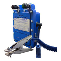
Operation and Care
Attach the grounding clamp at the end of the ground cable to the metal frame of vehicle, vessel, railcar, barge,
etc. The red light should turn off, and the green light should turn on when a proper ground connection is made.
At the same time, all auxiliary contacts will change state, allowing pump, blower, etc. to operate.
The indicator lights operate the following during normal conditions:
A good ground connection is not verified, and the controller is in a non-permissive state, do
not begin operation
A good ground connection is verified, and the controller is in permissive state, operation may
begin
No power to the grounding system, controller is in the non-permissive state, do not begin
operation
Both ground cables should be inspected regularly to ensure there is no damage to the insulation. Damaged
insulation may impair the proper operation of the grounding device. All hardware should also be inspected to
ensure proper tightness. Please refer to the Maintenance Schedule on page 6 for all recommended
maintenance and servicing.
LOCKOUT
(RED)
PERMISSIVE
(GREEN)
WHITE WIRE
CASE GROUND
10-32 3/8" SCREW
GROUND ROD
FOR REMOTE
LOCATIONS
TO
GROUND CLAMP
OR
DEADMAN
CONTROL
INTEGRITY GROUND (IG)
CONNECTION STUD
WHITE WIRE
10-32 3/8" SCREW
CASE GROUND AND IG STUD WIRES
MUST BE CONNECTED SEPARATELY
AT GROUND ROD UNDER SEPARATE
ACORN CLAMPS *NOT INCLUDED
GROUND
BUS
*PROTECTIVE
BOOT NOT
SHOWN
CASE GROUND AND IG STUD WIRES
MUST BE CONNECTED SEPARATELY
AT GROUND BUS
INSTALL WITH
RED AND GREEN
LIGHTS ON TOP
 Loading...