Setup for Operation
Connect the intake nozzle at the rear of the gas chamber to a suitable supply of gas. The gas should flow through
a pressure reducing valve prior to connection to the gas chamber. Gas pressure should not exceed 2 psi at the
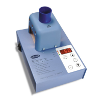
inlet valve of the gas chamber. Position your Stuart block heater on the base board, locating the two pins on the
bottom of the block heater onto the two location spigots on the base board. It is important that the block heater is
properly located to prevent misalignment of the needles later. The aluminium blocks should the centrally located
within the block heater, use the spacers provided.
Loosen the locking knob of the carriage and remove the gas chamber, lay the chamber upside down on a level
work surface. The needle matrix in the gas chamber has been designed to accommodate needles in various
patterns to suit the different sample configurations of the aluminium blocks. Each configuration has been labelled A
through F, please consult the guide below to know which configuration is appropriate for your aluminium blocks. As
an example, if you are using three SHT1/16 blocks for twelve 16mm tubes, you would need to insert needles in all
holes labelled C and all holes labelled D.
Tube Size and Number Insert Block code Hole label
0.5ml (6mm) x 30 SHT1/30 A
1.5ml (10mm) x 20 SHT1/22 B
2ml (12mm) x 20 SHT1/20 B
13mm x 20 SHT1/13 B
16mm x 12 SHT1/16 C & D
19mm x 8 SHT1/19 D,E & F
25mm x 6 SHT1/25 D & E
25mm x 6 SHT1/25 D & E
28mm x 6 SHT1/28 D & E
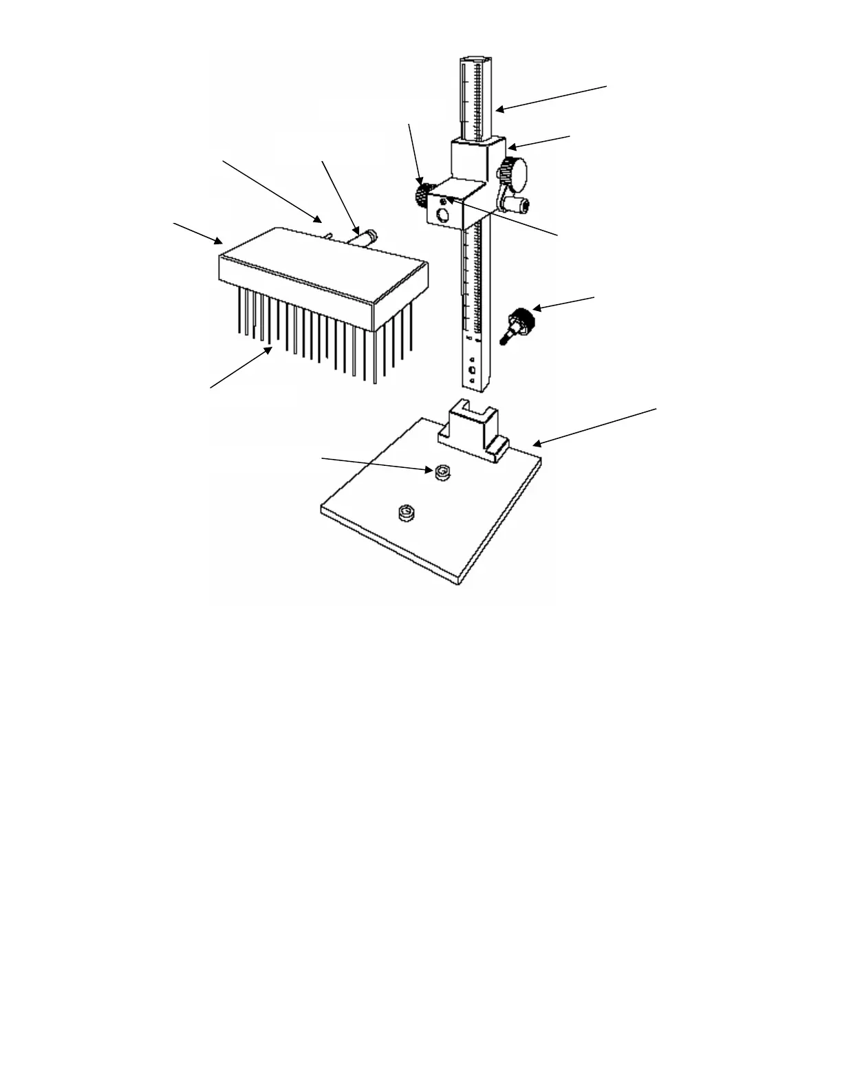
Column
Carria
e
Base board
Gas chambe
Base board
fastening knob
Locatin
in
Lockin
nut
Location s
i
ots
Positionin
in
Needles
Gas inlet