-
output voltage
at a
low internal output impedance. The output
socket
whlch follows
the output
transformer
is
mounted on the back of the
playback
ampllfier.
For
all adJustments
on the
playback
amplifler, see under E I
"Playback-Amplifier
Alignment".
D 4 AmpIifler Power SuppIy Unit
The
ampllfier
supply unlt conslsts of two
plug-in
unlts and supplles all the ampliflers lncluding
the oscillator. The HT-voltage ls electronlcally stablllzed to ensure hlgh stabllity of
performance
of the
ampliflers and
osclllator over
long
periods
of t1me.
D
4a
Amplifier Mains Sectlon
The
two malns transformers cause very little stray magnetic fields due to the use of
speclal C-
cores. They
provide
all
the operating
voltages for the record
and
replay
ampllflers as well
as
the
osclllator. The
sync-playback amplifiers
are supplied by
a
separate malns unlt. Sillcon
power
rectifters
provide
the HT
and
heater voltages
for
the
pre-ampllfler
stages.
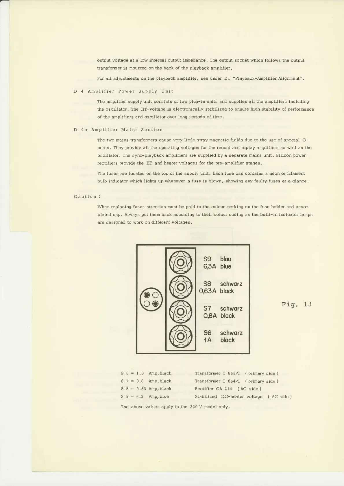
The
fuses are located on the
top of the
supply
unit. Each fuse cap contains
a
neon or filament
bulb indicator whlch
llghts
up
whenever
a
fuse
ls blown, showlng any
faulty fuses
at a
glance.
Caution
!
When replacing fuses
attention
must be
pald
to the colour
marking
on the
fuse
holder and
asso-
clated cap. Always
put
them back
accordlng
to thelr colour coding as the built-ln indlcator lamps
are designed
to work on different voltages.
@
@
@
@
59
blou
6,34
blue
SB
schworz
0,634 block
57 schnrorz
O,8A block
56
schworz
'lA
block
Fig. 13
S 6
=
1.0 Amp,black
Transformer
T 863/I
( primary
slde
)
S 7
=
0.8 Amp,black Transformer I 8644
(
prlmary
side
)
S 8
=
0.63 Amp,black
Rectlfler
OA 2I4
(AC
side
)
S 9
=
6.3 Amprblue
Stabilized DC-heater voltage
(
AC side
)
The
above
values
apply
to the 220 V model only.
 Loading...


