a-
tortlon Measurements".
The relays
RL1
and
RL2 swltch the
blas current accordlng
to the
select-
ed tape speed.
To
enable a
recordlng to be made in sync
with one or
more existing tracks,
the record heads
are
connected
via the contacts of
the relays RA 1,
RA
2,
RA 3
and
RA
4
to the inputs
of the correspon-
ding sync-playback
amplifiers.
For thls
purpose
the
record head is beinq used as a
replay head
ard the
frequency correction
networks are contalned
in the correspondlng sync-playback amplifler.
When the
"record"
selector key
of
any
channel ls
pressed,
the
approprlate
relay RA
(
1,
2,
3, 4
'l
swltches
the record
head to the corresponding
blas
supply
and
recordlng
ampllfler
(
see ctrcult
diagram 7.837.500
oscillator
)
,
at
the
same
time the corresponding
sync-playback amplifier
is
short-ctrcuited.
Durlng
recording these
keys
are
electrically Iocked and
the channels cannot be
switched
in
or out of
"record".
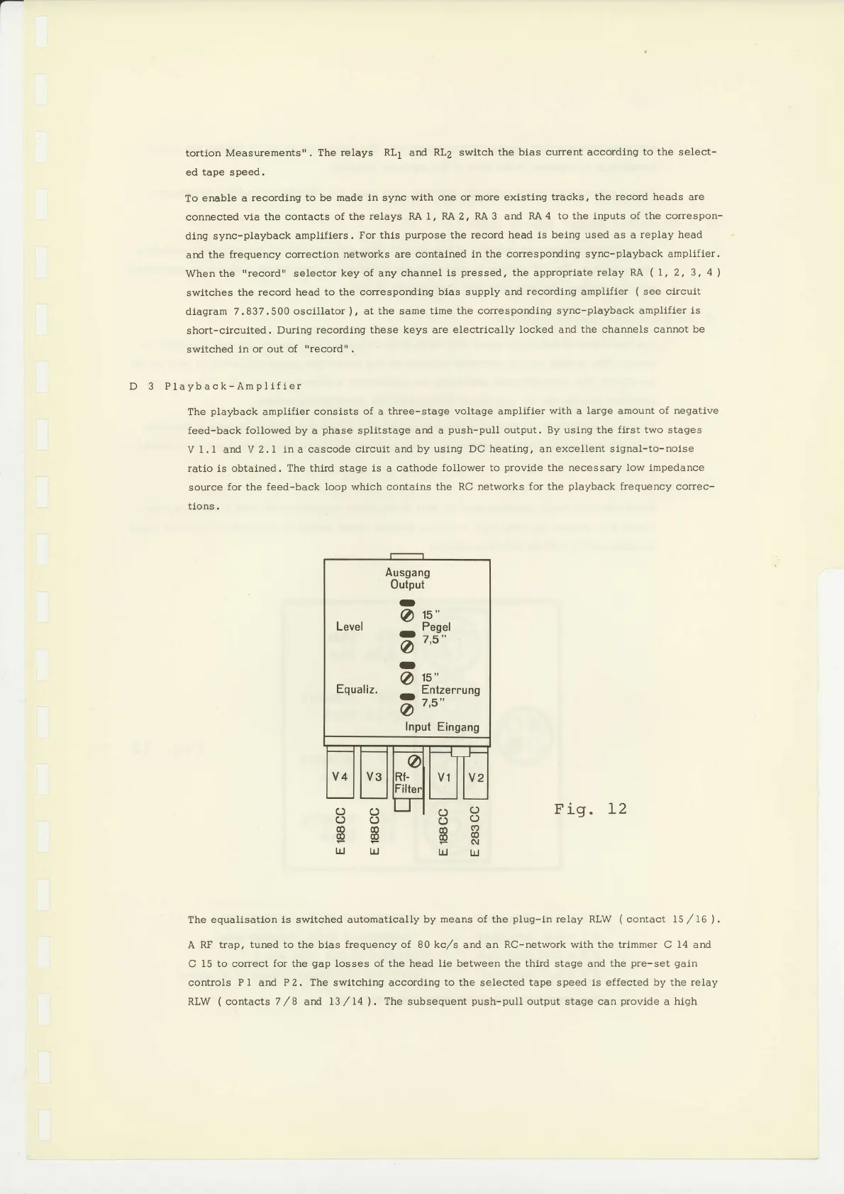
D 3 Playback-Ampllfler
The
playback
ampllfler
conslsts of a three-stage
voltage
amplifler
wlth
a
large
amount
of negative
feed-back
followed by
a
phase
splitstage ard a
push-pull
output. By uslng
the first two
stages
V 1.
I
and V 2.1
in
a
cascode clrcult and by
using DC heating, an excellent signal-to-noise
ratlo ls
obtained. The third stage is a
cathode follower to
provlde
the necessary low impedance
source
for
the
feed-back loop whlch contains
the RC networks for the
playback
frequency
correc-
t10ns.
Fig. L2
The
equalisation 1s swltched automatically
by means of the
plug-in
relay RLW
(
contact 15
/
16
)
.
A
RF trap, tuned to the blas
frequency of
80
kc,/s
and an
RO-network with the trlmmer
C
14
and
C 15
to
correct
for the
gap
losses of the head Ile between the thlrd stage and the
pre-set galn
controls
PI
and
P2. Theswltchingaccordlngtotheselectedtapespeediseffectedbytherelay
RLW
(
contacts
7
/8
ard
13
/14
)
.
The subsequent
push-pull
output
stage
can
provide
a
high
c)!?
c)v
ER
t!
uJ
oc)
oc)
@@
oo
lrl
UJ
Ausgang
Output
-
At"
Level
-
lp3l
-
o9"
Equailz.
o
Eilzerrung
a""
Input
Eingang
 Loading...


