a-
D 2 Oscillator
The
high frequency of
approximately
80 kc,/s for erase
and
bias
currents
is
produced
by a very
stable and symmetrical
push-pull
circuit
using two
double trlodes E 188 CC
(
V3
and
V6
).
The
oscillator coil, the
feed
back coll and the output
winding for
the erase current
are
wound on
a
ferrlte
core
I.337
.764.
The erase heads
are
fed directly from the
secondary
wlndlng
of the Trans-
former
(
which
forms
the lnductance of the tuned circuit
)
via the contacts of the relays RAl,
RAz,
RA3 and
RA4.
An inductance
D
(
I,
2, 3.
4
)
is switched as dummy-erase-head into circuit
by
the
contacts of
the
appropriate
relay
RA
(
1, 2, 3
,
4
)
for
any
channel that
is
not
swltched lnto
"record"
. This
coil
D
is
made to have the
same inductance and
Q-factor
as the corresponding erase head,
(
Thls
adjustment
is made in the factory
),
This
prevents
sudden changes ln level and achieves
a
con-
stant
loading of the osciilator regardless of the number of
channels
which
are belng swltched into
"record".
In
order to achieve the best
possible
signal-to-noise
ratio, the blas
current
for
the
record
head is
not taken directly
from
the oscillator.
Instead,
the bias for each head,
passes
through a
separate
push-pull
stage
with
a
tuned-plate
circuit.
which
reduces
the harmonlc dlstortlon of the high fre-
quency
bias to
a
value well below the level which could
cause any hlss:
These tuned RF-stages make it
possible
to dispense with the usual bias
symmetry adjustment
which tends to be unstable and would need to be
re-set from
time to time.
nrty
Lops ,,-,-= in excess of the inherant tape noise can only
be caused by DC-magnetlsatlon of
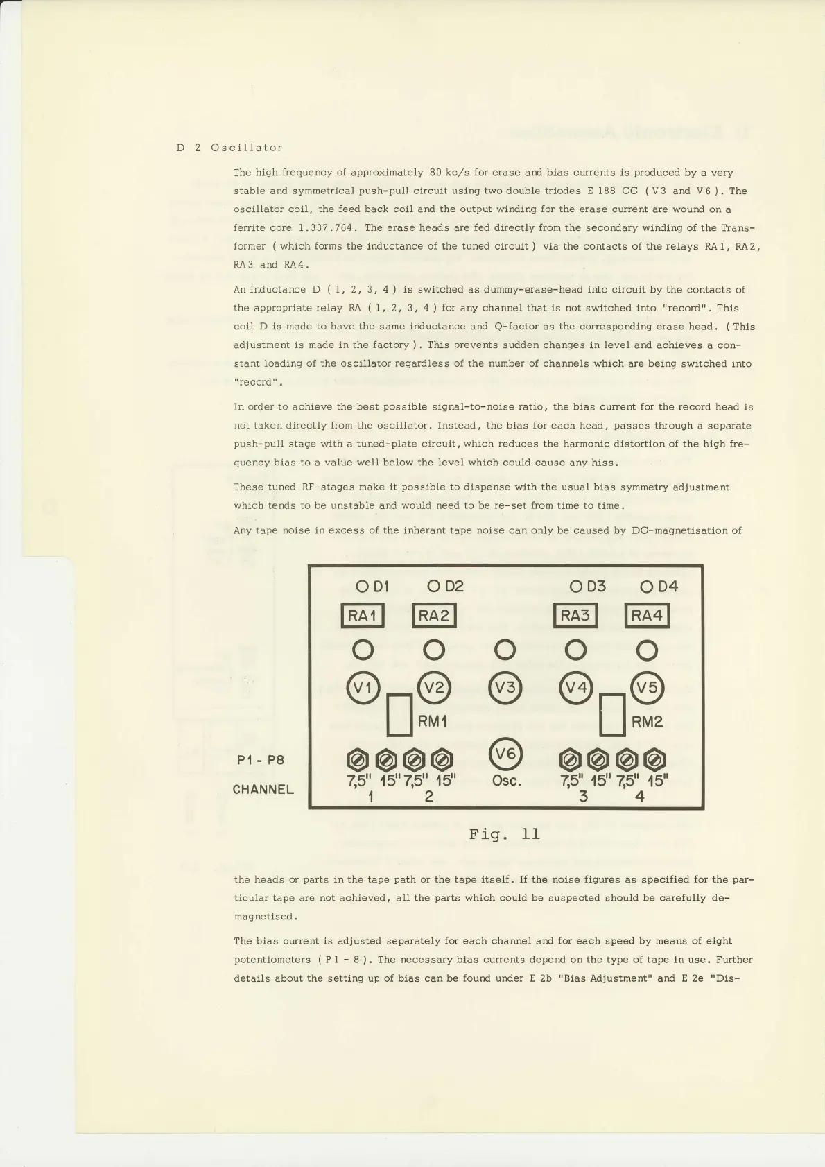
Pt-P8
CHANNEL
Fig. 11
the heads or
parts
inthe tape
path
or the tape itself. If the noise
figures
as specified
for the
par-
ticular tape
are
not
achieved, all
the
parts
which could be
suspected should be carefully de-
*^^*^+r^^J
rlqvrrsLrssu.
The bias current ls adjusted separately
for
each channel and
for
each speed by means
of
elght
potentlometers (Pl
-
I
).
The
necessarybias
currents depend onthetype oftape 1nuse. Further
details
about
the
setting
up of bias can be
fourd
under E 2b
"Bias
MJustment"
and
E 2e
"Dls-
oDr
oDz
0D3
0D4
@@ @1 @
ooooo
@...|@ @
@r-.|@
l_l
nur
l_l
nuz
@@@@
@
@@@@
25"
.15'7,5"
15' osc.
7,5"
,15'25"
45"
1234
 Loading...


