,-
D Electronic
Assemblies
The
electronlcs, each
formlng
a
complete sub-unlt,
Ile neatly
ln the lower
portlon
of the angle
lron
frame. They
are
the
record
and
replay ampllflers,
the osclllator and the ampllfler
powersupply
unit whlch ls ln two sectlons.
All these units are
equlpped
wlth
contact strips ard can
be removed
by
presslng
the red locklng key and
pulltng
the unlt forward.
When replaclng
an ampllfler,
lt locks
ln automatlcally.
During these operatlons,
the recorder should
be swltched off to avoid
magnetis-
lng the
heads, due to transient
pulses,
The
various
ampllfiers,
etc.,
are
lnter-connected by
means
of a cable
former. See
clrcuit dlagram 7,837.380.
The ampllflers
are equipped
wlth triodes throughout, and
large
amounts
of negatlve
feed-back make
the ctrcuits
vlrtually irdeperxient
of valve characterlstlcs.
To enable
the unlts to be servlced
or tested outslde the
recorder, two adaptor cables are avallable.
They can
be
supplted
upon
request. The foflowing descriptions
refer to one channel. The
four
channels are identical.
D
I Record Ampltfler
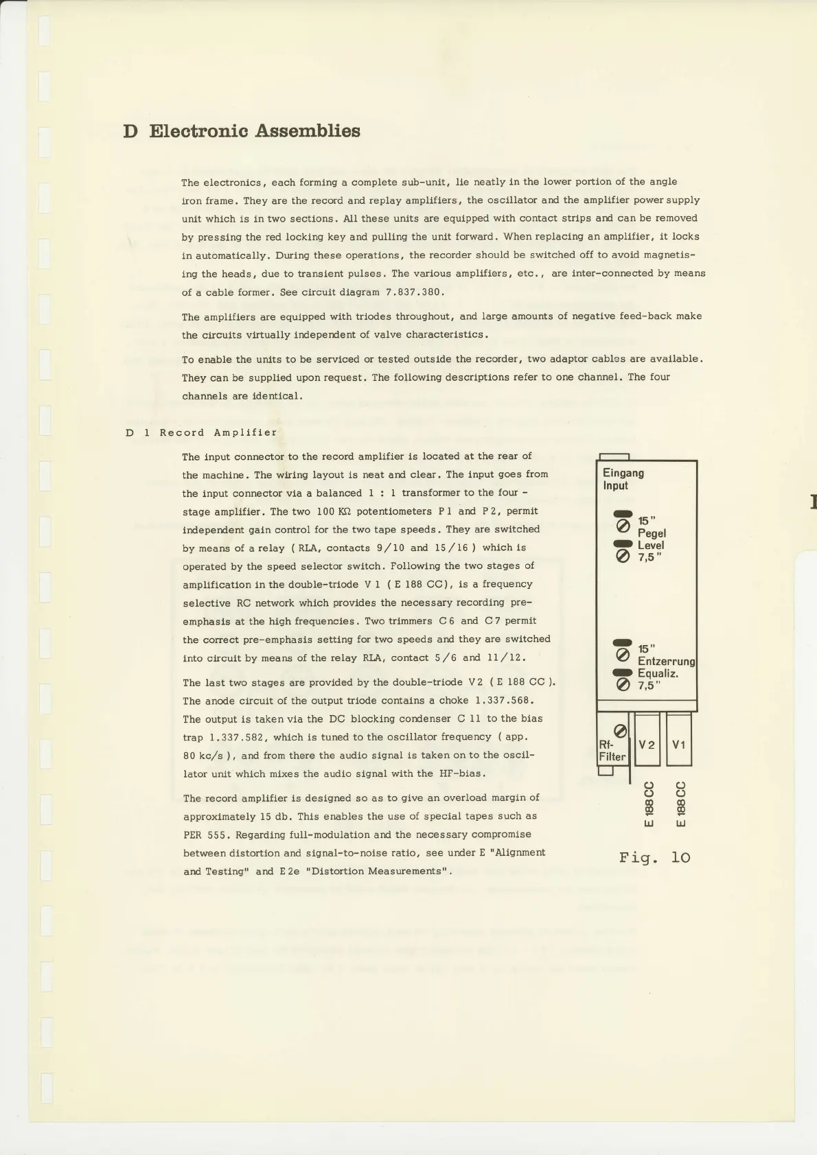
The lnput
connector to the
record
ampllfler
ls located at
the
rear
of
the machlne.
The wlrlng layout ls
neat
and
clear. The input
goes
from
the input connector
via a balanced
I :
I transformer to
the four
-
stageampllfler.
Thetwo
l00Kfl
potentlometers
PI ard
P2,
permlt
lndeperdent
galn
control
for
the
two tape speeds.
They
are
switched
by means of a
relay
(
RLA, contacts 9/L0 and
15,/16
)
whtch ls
operated
by the speed selector
switch. Pollowlng
the two stages
of
ampllflcatlon
ln the double-trtode
V 1
(
E f88 CC),
is
a
frequency
selective
RC network
which
provldes
the necessary
recordlng
pre-
emphasls at
the high
frequencles. Two
trlmmers C6
and
C7
permit
'
the correct
pre-emphasts
settlng
for two
speeds
ard
they
are
swltched
lnto clrcult
by means of
the relay RLA, contact 5,/6
and Ll
,/lZ.
The last two stages are
provlded
by
the double-triode V 2
(
E I88 CC
).
The anode
circuit of the
output trlode contalns a
choke I.337.568.
The output is
taken vla the
DC blocklng cordenser C
lI to the blas
trap 1.337.582, whlch
is tuned to the
osctllator
frequency
(
app.
80 kc,/s
),
and
from
there
the
audio
slgnal ls
taken on to the oscll-
lator unlt
which mtxes the audlo slgnal
with the HF-bias.
The record amplifler
is deslgned so as
to
give
an overload
margln of
approxlmately
15 db. This
enables the use of special
tapes
such as
PER
555.
Regardlng
full-modulatlon and the
necessary compromlse
between
dlstortlon and slgnal-to-noise
ratlo, see under
E
"Alignment
ard Testing" and
E 2e
"Dlstortlon
Measurements".
I
c)()
oo
@@
@@
UJ UJ
Fig. Io
 Loading...


