17
BATTERIES
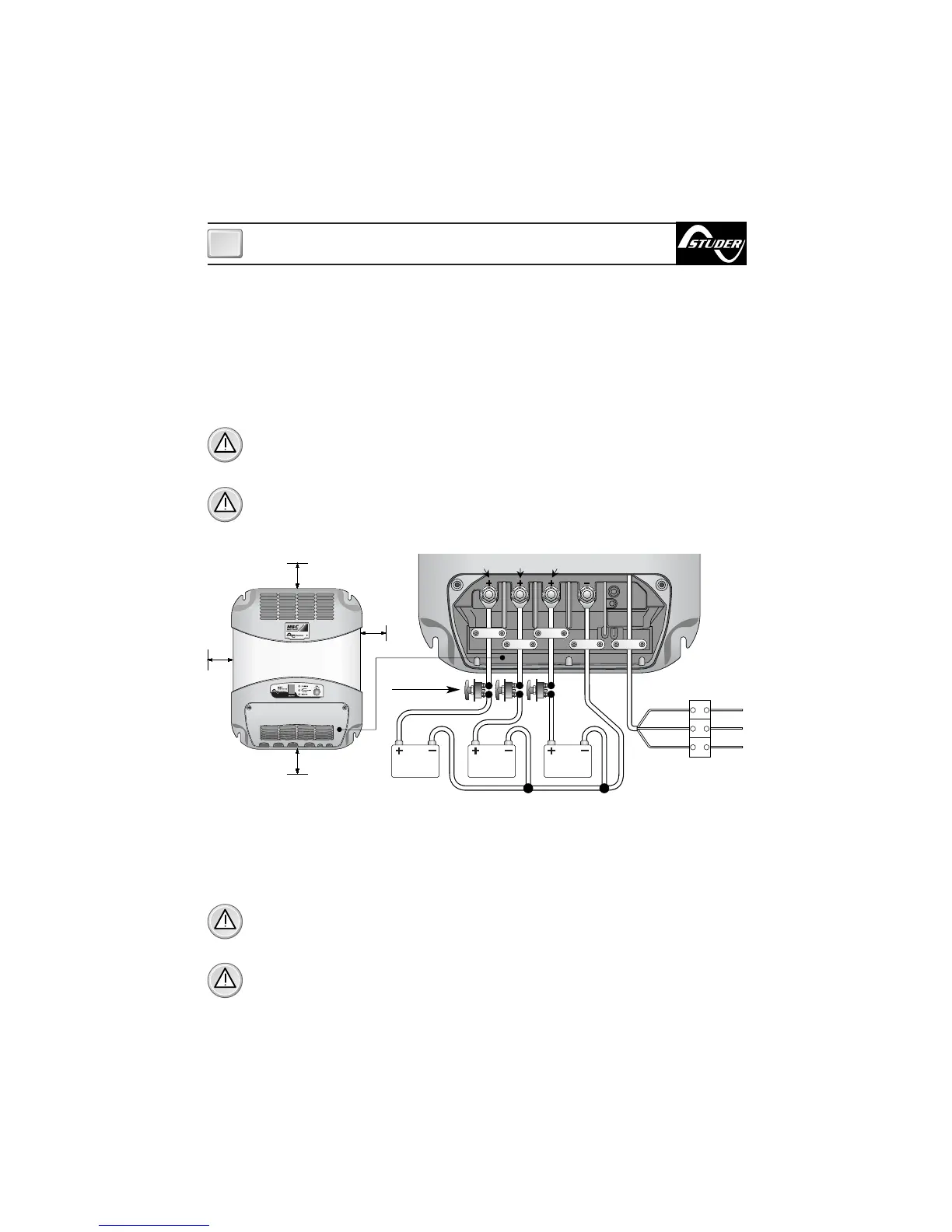
To access the output terminals it is necessary to remove the cover by loosening the two screws
which hold it on top (see fig. 1 Part A). Before making the connections to the cables from the bat-
tery, loosen or remove the cable clamps by loosening the screws which fix it to the base (Fig.1
Part B).
WARNING: during charge, batteries can generate explosive gases, therefore avoid
sparks or naked flames. Provide adequate ventilation to the battery area whilst charg-
ing.
WARNING: before connecting the batteries check the terminals of the cables from the
battery. Reversing the terminals, could seriously damage the battery charger even if pro-
tected by fuses.
INSTALLATION
GB
EQUIPMENT SUPPLY
The equipment already includes a power cable for AC supply. For connections to an AC supply
see fig.2. Before powering up the battery charger check that the power supply voltage, de-
scribed on the rating label, corresponds to that supplied by the AC supply source.
In the electrical circuit a two-pole switch must be installed for the sole use of switching the
equipment ON & OFF. The insulation between the contact points of the connections of the AC
supply must be at least 3 mm. The connections to the AC supply must be carried out according
to local electrical codes.
WARNING: before connecting or disconnecting the cables from the electrical terminals of
the battery charger, make sure that the equipment is disconnected from the AC mains and
the batteries.
WARNING: in cases where the power supply cable could be damaged, have this
changed by a “Studer Innotec” service centre. In order to avoid accidents, the equip-
ment must only be opened by authorised personnel.
5 cm
5 cm
5 cm
5 cm
FIG.2
battery
n° 3
battery
n° 2
battery
n° 1
Battery switches
Blue
Yellow
Green
Brown
Neutral
Earth
Live
SLAVE B SLAVE A
MASTER