21
GB
OPERATING
CONTROL PANEL
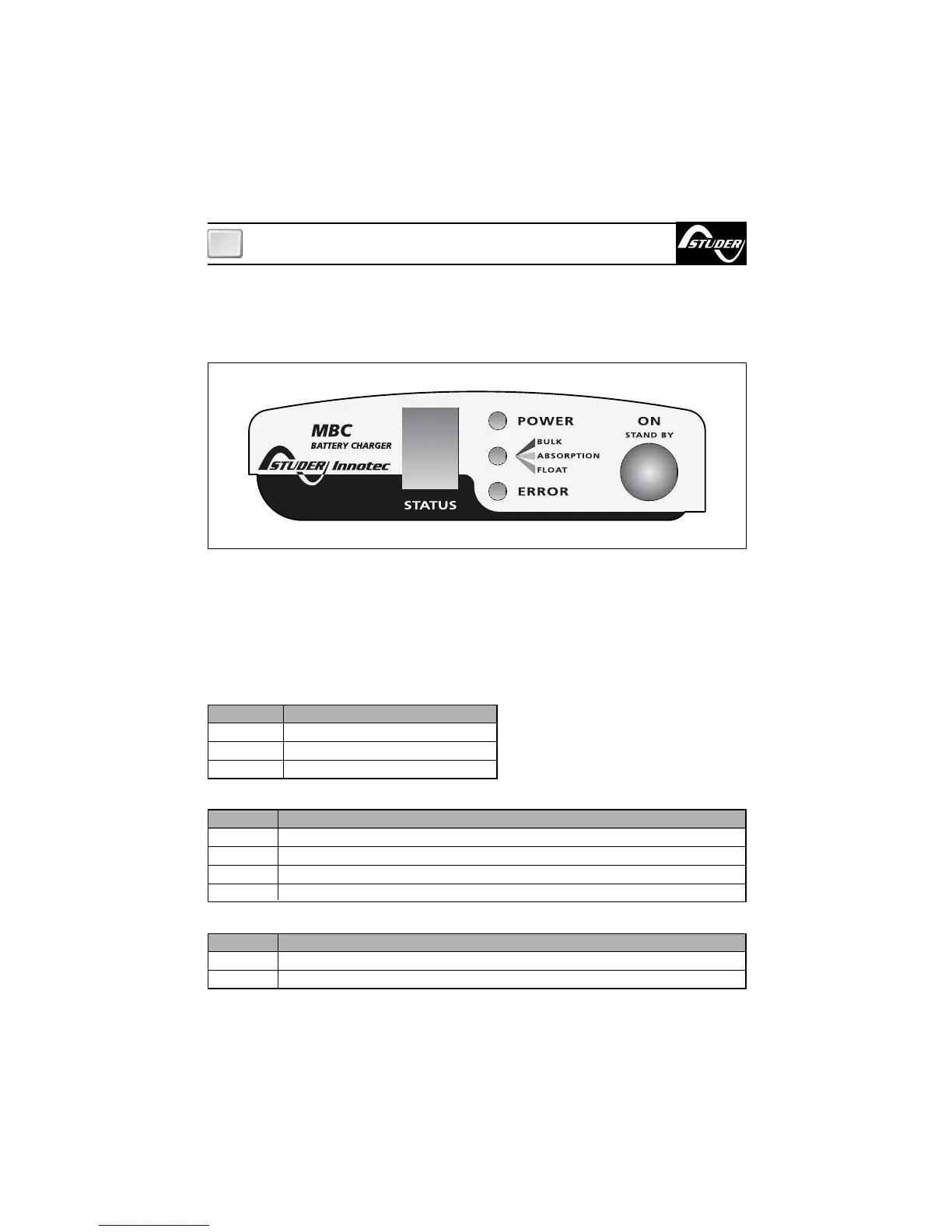
The control panel is made-up of three LED, a 7 segment display and a button:
POWER LED, CHARGE PHASE LED (BULK, ABSORPTION, FLOAT) ERROR LED, STATUS display
and ON/STAND-BY button (see fig.4).
CHARGE PHASE LED (BULK, ABSORPTION, FLOAT)
ERROR LED
Description
No output power
BULK phase - charge at constant current
ABSORPTION phase - charge at constant voltage
FLOAT phase - float charge
FIG.4
LED Colour
OFF
Red
Orange
Green
LED Colour
OFF
Red
Description
No problem with manual reset
Problem with manual reset (see error codes)
The information supplied by the LEDS are listed as below:
POWER LED
LED colour
OFF
Green
Flashing
Description
No mains power
Power ON
Battery charger in stand-by mode
ON/STAND-BY BUTTON:
Use this button to put the battery charger in stand-by mode. To activate this mode simply
press the button quickly (press and release in less than one second). To take the battery
charger out of stand-by mode, press the button quickly again or disconnect the battery charg-
er from the AC power supply and then connect it up again.