^¥y[D)[i[^ PI
4/1
4.
MECHANIK
Bedingt
durch das stabile
Druckguss-Chassis und
das
3-Motoren-Laufwerk
ergibt
sich
ein weit-
gehend
wartungsfreier
mechanischer
Teil.
Die
Einstellungen
und
Messungen
beschranken
sich
auf die
wenigen
beweglichen
Teile.
4.
TAPE
TRANSPORT MECHANISM
Thanks
to
the rigid diecast chassis and the
3-motor
transport mechanism, the mechanics of
the recorder do
not require frequent servicing.
Adjustments and measurements are
confined
to
a
few moving
parts.
4.
MECANIQUE
Grace
a
un chassis stable
en
fonte injectee et a
un mecanisme
equipe
de 3
moteurs, la partie
mecanique de
I'appareil
ne necessite
pratique-
ment
aucun
service.
Les
quelques
reglages
existants ne
concernent que les pieces en
mouvement.
4.1. Kopftrager
4.1.1.
Bandfijhrungen
—
Bandfijhrungen reinigen,
Bandfuh-
rung(A) nicht
verstellen.
Wenn
notig, kann die
Bandfuhrung mit
einem
Kreuzschlitz-Schrauben-
zieher
vom Kopftrager gelost werden
(2
Schrau-
ben, Fig.
4.1
.—
1
).
—
Tacho-Rolle
reinigen
4.1.
Headblock
4.1.1.
Tape guides
—
Clean tape
guides,
take
care
not
to alter
the
adjustment of
guide
(a). The
tape guide
may
be removed
from
the headblock
after un-
doing
its Phillips
head
mounting
screws
(2
screws,
fig.
4.1
.—1
).
-
Clean the
tacho
roller
rs)
4.1. Support
des t§tes
4.1.1.
Gu ides de bande
Nettoyez
les
guides
de bande,
ne
pas
deregler
le
guide de bande
(X), qui si necessaire ne
sera
demonte
qu'avec son support,
a
I'aide d'un
tournevis
a
croix
(2
vis, fig. 4.1
.—1
).
Nettoyez
la roue tachymetriquef
B
4.1.2.
To nkopf
befest igu ngen
Die
Tonkopfe sind auf das
Kopftragerchassis ge-
schraubt.
Bei abgenommenem
Kopftragerchassis
konnen die
Tonkopfe mit
der Zentrums-
schraube gelost
werden.
Wird der
Aufnahme-
Oder Wiedergabe-
kopf ausgewechselt, so
ist
die
Maschine vorzugs-
weise an die
nachste Werksvertretung
zur Neu-
justierung
einzusenden.
4.1.2.
Head
mounting
The
magnetic heads are attached
to the head-
block
chassis with one
central mounting screw
per
head.
To remove a
magnetic head,
the head-
block chassis has
to
be
separated
from the re-
corder.
To
have
the recording and
reproducing
heads replaced, it is advisable
to send
the re-
corder
to the
nearest REVOX service facility to
ensure
their correct realignment.
4.1.2.
Fixation des tdtes
Les t^tes sont
vissees sur
le
support
des tetes.
Les tetes
peuvent §tre retirees en
devissant ia
vis
centrale apres
avoir
ote le support
des tetes.
S'il est
necessaire de
changer les
tetes
d'enregistrement
ou de lecture
il est conseille de
faire parvenir votre appareil au
service apres
vente le
plus proche afin d'y
proceder aux re-
glages
necessaires.
4.2. Bremsen (STOP)
Die
Bremsen
sind
wirksam, wenn
der Brems-
magnet stromlos ist.
—
STOP-Taste
drucken.
4.2.
Brakes
(STOP)
The brakes are applied
as
long as the
brake
solenoid is not energized.
—
Press button STOP.
4.2. Freins (STOP)
Les
freins
agissent lorsque
I'electro-aimant
des
freins
n'est
pas alimente.
—
Presser la touche
STOP.
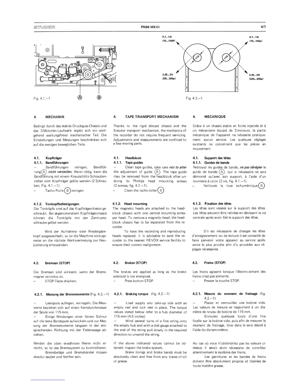
4.2.1. Messung
der
Bremsmomente(Fig.
4.2.—
1 )
4.2.1. Braking torque
(fig. 4.
2.-1
)
—
Leerspule
auflegen,
verriegeln. Die Mess-
werte beziehen sich auf
einen Kerndurchmesser
der
Spule
von 1
1 5
mm.
—
Einige
Windungen einer
f einen Schnur
auf
die leere Bandspule
aufwickein und
zur Mes-
sung
der Bremsmomente
langsam
in
der
ent-
sprechenden Richtung
mit der Federwaage ab-
ziehen.
Werden
die oben erwahnten
Werte
nicht er-
reicht,
so ist das
Bremssystem
zu
kontrollieren.
Bremsbelage
und
Bremsbander mussen
absolut
sauber und
fettfrei sein.
—
Load
supply
and take-up side
with
an
empty
reel and lock
reel
in place.
The
torque
values
stated below
refer
to a
hub diameter
of
1
1 5
mm
(4.5
inches).
—
Wind
several turns of
a
fine
string
onto
the empty
hub and with
a
dial
gauge attached
to
the end of
the string
pull slowly
in the required
direction
to
unwind
the string.
If
the
above
indicated
values
cannot be ob-
tained, inspect
the brake
system.
Brake linings
and
brake
bands must be
absolutely clean
and
free
from
any traces
of
oil
or grease.
4.2.1.
Mesure du
moment de
freinage
(fig.
4.2.-1)
—
Placez et
verrouillez une
bobine vide.
Les
valeurs de
mesure se
rapportent
a
un dia-
metre de
noyau de
bobine de
1
1 5
mm.
Enroulez
quelques tours
d'une
fine
ficelle sur la bobine
vide, puis
afin de mesurer
le
moment de freinage,
tirez dans
le sens desire a
I'aide
du
dynamometre.
Au
cas ou
vous
n'obtiendriez pas les
valeurs
ci-
dessus il serait alors
necessaire de
controler
attentivement
le
systeme des freins.
Les garnitures
et
les bandes
de
freins
doivent
§tre absolument prop res
et
liberees
de
toute matiere
grasse.
 Loading...