iTrOJ[D)[E[M]
PR99
MKIII
5/6
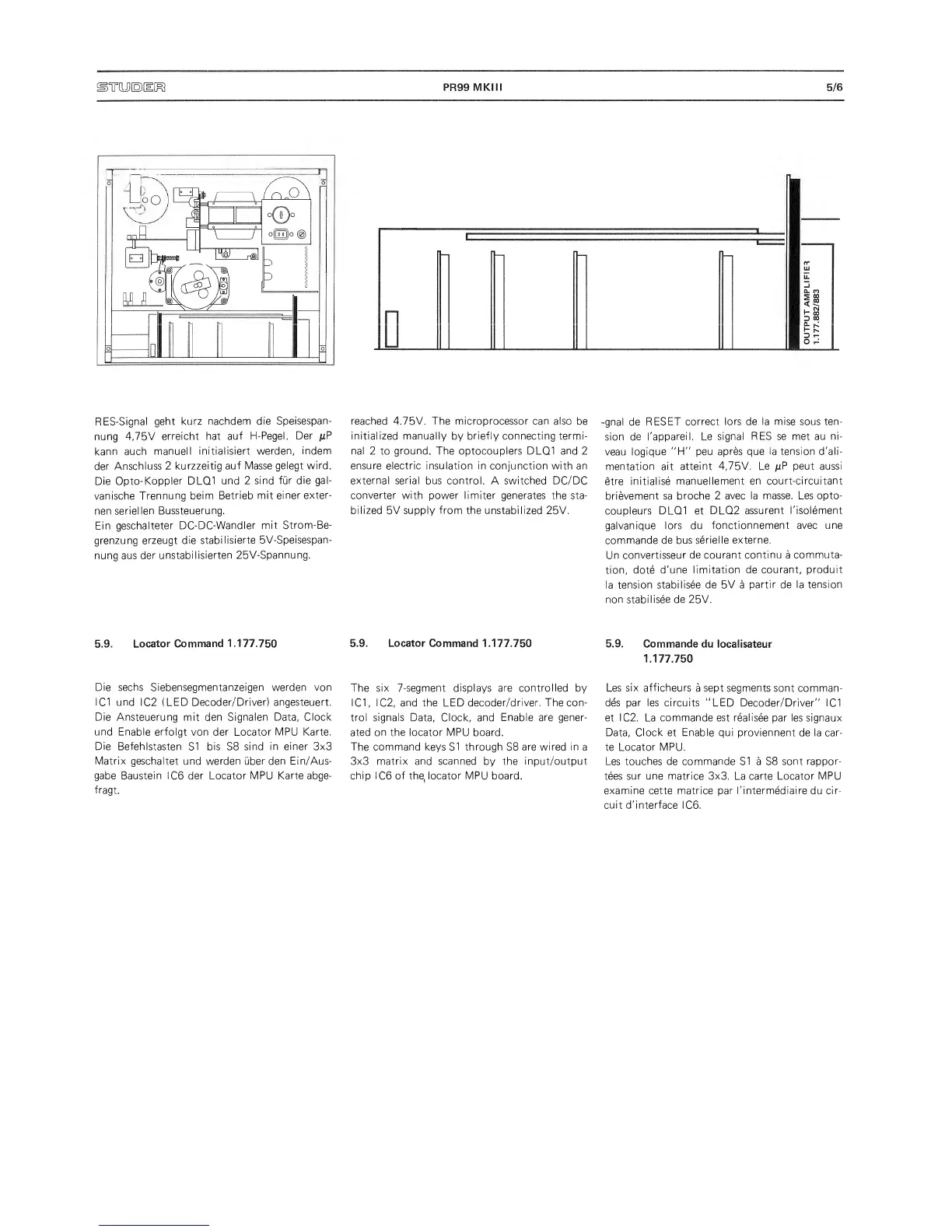
RES-Signal
geht kurz
nachdem die
Speisespan-
nung
4,75V
erreicht hat auf
H-Pegel.
Der
juP
kann
auch
manuell
initialisiert
werden, indem
der
Anschluss
2
kurzzeitig auf Masse
gelegt wind.
Die
Opto-Koppler DLQ1
und
2
sind fur die
gal-
vanische
Trennung beim
Betrieb
mit
einer exter-
nen
seriellen
Bussteuerung.
Ein
geschalteter
DC-DC-Wandler
mit Strom-Be-
grenzung erzeugt
die
stabilisierte
5V-Speisespan-
nung aus
der
unstabilisierten
25V-Spannung.
5.9.
Locator
Command 1.177.750
Die sechs
Siebensegmentanzeigen werden
von
I
Cl und
IC2 (LED
Decoder/Driver) angesteuert.
Die
Ansteuerung mit den Signalen Data, Clock
und
Enable erfoigt von der Locator MPU Karte.
Die
Befehlstasten
SI
bis
S8
sind in
einer
3x3
Matrix geschaltet
und
werden
uber
den Ein/Aus-
gabe Baustein ICG der Locator MPU
Karte abge-
fragt.
reached
4.75V. The microprocessor
can also
be
initialized manually
by
briefly connecting
termi-
nal 2 to
ground. The
optocouplers DLQ1 and 2
ensure electric insulation in conjunction with an
external serial
bus control.
A
switched
DC/DC
converter with
power
limiter generates
the sta-
bilized
5V
supply from the
unstabilized 25V.
5.9.
Locator
Command 1.177.750
The six 7-segment displays are controlled
by
I Cl,
IC2,
and the LED decoder/driver.
The con-
trol signals
Data, Clock, and
Enable are gener-
ated on the locator
MPU
board.
The command keys SI through
S8
are
wired
in
a
3x3 matrix and scanned
by
the input/output
chip
I C6
of the, locator MPU board.
-gnal de
RESET correct
lors de la mise sous ten-
sion de
I'appareil. Le
signal
RES
se met au
ni-
veau
logique
"H”
peu
apres que la tension d'ali-
mentation ait
attaint
4,75V. Le
/iP peut aussi
etre
initialise
manuellement
en court-circuitant
brievement sa broche
2 avec la
masse. Les opto-
coupleurs DLQ1 et
DLQ2
assurent
I'isolement
galvanique
lors du
fonctionnement
avec une
commande
de
bus
serielle externe.
Un
convertisseur de
courant
continu
a
commuta-
tion, dote
d'une
limitation de courant,
produit
la tension
stabilisee de 5V
a
partir de la tension
non stabilisee
de 25V.
5.9.
Commande
du local isateur
1.177.750
Les
six afficheurs
a
sept segments
sont comman-
des par les circuits "LED
Decoder/Driver" IC1
et IC2.
La
commande est real
i see par les signaux
Data,
Clock et Enable
qui
proviennent
de la car-
te Locator MPU.
Les
touches de commande SI
a S8
sont rappor-
tees
sur une
matrice
3x3.
La
carte Locator
MPU
examine
cette matrice par
I'intermediaire
du
cir-
cuit d'interface
ICG.
 Loading...