)TO[d)[E[M]
PR99 MKIII
5/5
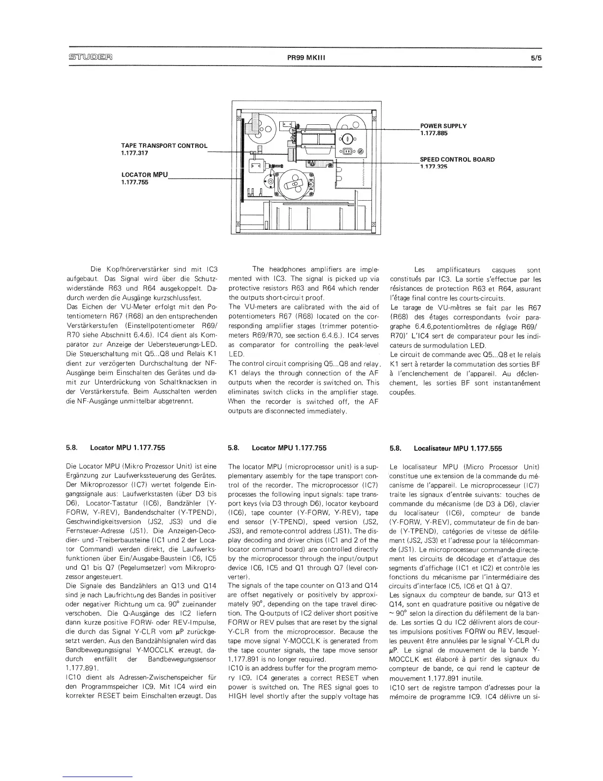
POWER
SUPPLY
1.177.885
SPEED
CONTROL BOARD
1 177
325
Die
Kopfhorerverstarker
sind mit
ICS
aufgebaut. Das Signal
wird
uber die
Schutz-
widerstande R63
und
R64
ausgekoppelt.
Da-
durch werden
die Ausgange kurzschlussfest.
Das Eichen der VU-Meter
erfoigt
mit
den Po-
tentiometern
R67 (R68)
an den entsprechenden
Verstarkerstufen
(Einstellpotentiometer R69/
R70
siehe Abschnitt
6.4.6).
IC4
dient als
Kom-
parator zur Anzeige
der Uebersteuerungs-LED.
Die
Steuerschaltung
mit Q5...Q8 und
Relais
K1
dient
zur verzogerten Durchschaltung der
NF-
Ausgange
beim Einschalten des Cerates und
da-
mit zur Unterdruckung
von Schaltknacksen in
der
Verstarkerstufe. Beim Ausschalten werden
die NF-Ausgange
unmittelbar abgetrennt.
5.8.
Locator
MPU
1.177.755
Die Locator
MPU (Mikro
Prozessor
Unit) ist eine
Erganzung
zur
Laufwerkssteuerung des
Cerates.
Der
Mikroprozessor
(IC7)
wertet folgende
Ein-
gangssignale
aus: Laufwerkstasten
(uber
D3 bis
D6),
Locator-Tastatur
(IC6),
Bandzahler (Y-
FORW, Y-REV), Bandendschalter
(Y-TPEND),
Ceschwindigkeitsversion
(JS2, JS3)
und die
Fernsteuer-Adresse
(JS1).
Die Anzeigen-Deco-
dier-
und
-Treiberbausteine (I Cl und 2 der Loca-
tor
Command)
werden
direkt,
die Laufwerks-
funktionen
uber
Ein/Ausgabe-Baustein IC6,
IC5
und
Q1 bis
Q7
(Pegelumsetzer) vom Mikropro-
zessor
angesteuert.
Die
Signale
des Bandzahlers an Q13 und Q14
sind
je
nach Laufrichtung
des Bandes
in positiver
Oder
negativer
Richtung urn
ca.
90°
zueinander
verschoben.
Die Q-Ausgange des IC2 liefern
dann
kurze positive FORW- oder REV-1 mpulse,
die
durch das Signal
Y-CLR
vom /LtP zuruckge-
setzt
werden.
Aus
den Bandzahlsignalen wird
das
Bandbewegungssignal
Y-MOCCLK erzeugt,
da-
durch
entfallt
der Bandbewequnqssensor
1.177.891.
I CIO
dient als Adressen-Zwischenspeicher fur
den
Programmspeicher
ICO.
Mit
IC4
wird
ein
korrekter
RESET beim Einschalten erzeugt. Das
The
headphones
amplifiers
are imple-
mented with
ICS. The
signal is
picked
up
via
protective
resistors
R63
and
R64
which
render
the
outputs short-circuit
proof.
The
VU-meters
are calibrated
with
the aid of
potentiometers R67
(R68)
located on the cor-
responding
amplifier
stages (trimmer
potentio-
meters R69/R70,
see section
6.4.6.).
IC4
serves
as
comparator for controlling
the
peak-level
LED.
The control
circuit
comprising
Q5...Q8
and
relay.
K1 delays
the
through
connection
of the
AF
outputs when
the
recorder is
switched
on.
This
eliminates
switch
clicks
in
the amplifier
stage.
When
the
recorder is
switched
off, the AF
outputs
are
disconnected immediately.
5.8.
Locator
MPU 1.177.755
The locator
MPU
(microprocessor
unit)
is
a sup-
plementary assembly for the tape transport con-
trol of the recorder. The microprocessor
(IC7)
processes
the
following input signals:
tape
trans-
port keys (via D3 through D6), locator keyboard
(IC6), tape
counter
(Y-FORW,
Y-REV),
tape
end sensor (Y-TPEND),
speed
version
(JS2,
JS3),
and remote-control
address (JS1).
The dis-
play decoding
and driver chips
(I
Cl
and
2 of the
locator command
board) are
controlled directly
by
the microprocessor through the input/output
device
IC6, IC5
and Q1 through
Q7
(level con-
verter).
The signals of the
tape
counter
on
Q13 and
Q14
are
offset negatively
or
positively
by
approxi-
mately
90°,
depending on the
tape
travel direc-
tion. The
Q-outputs of IC2
deliver short positive
FORW or
REV
pulses that are reset
by
the signal
Y-CLR from the
microprocessor.
Because
the
tape
move
signal Y-MOCCLK is generated from
the
tape
counter signals,
the
tape move sensor
1.177.891
is
no longer required.
I CIO is an address buffer for the program memo-
ry
IC9. IC4
generates
a
correct
RESET when
power is
switched
on. The
RES signal goes to
F1IGFI level
shortly
after
the supply voltage has
Les
amplificateurs
casques
sont
constitues
par
ICS.
La sortie s'effectue
par les
resistances
de protection R63
et R64,
assurant
I'etage final
contre les
courts-circuits.
Le
tarage
de
VU-metres se
fait
par les
R67
(R68)
des etages
correspondants
(voir
para-
graphe
6.4.6,potentiometres
de
reglage
R69/
R70)'
L'IC4 sert
de comparateur
pour les indi-
cateurs
de
surmodulation
LED.
Le
circuit
de commande avec
05.
..08
et
le
relais
K1
sert
a
retarder la
commutation
des sorties BF
a I'enclenchement
de
I'appareil.
Au
d4clen-
chement,
les sorties
BF sont
instantanement
coupees.
5.8.
Locaiisateur
MPU 1.177.555
Le locaiisateur
MPU (Micro
Processor
Unit)
Iconstitue
une extension
de la
commande
du
me-
canisme de I'appareil.
Le microprocesseur (IC7)
traite les signaux
d'entree
suivants;
touches de
commande
du mecanisme
(de
D3
a D6),
clavier
du locaiisateur
(IC6),
compteur de bande
(Y-FORW, Y-REV),
commutateur
de fin de ban-
de
(Y-TPEND),
categories
de
vitesse
de defile-
ment (JS2, JS3) et
I'adresse
pour la telecomman-
de
(JS1 ). Le microprocesseur
commande directe-
ment les circuits
de
decodage et
d'attaque des
segments d'affichage (IC1 et
IC2) et controle les
fonctions
du
mecanisme par I'intermediaire
des
circuits d'interface
IC5, IC6
et 01
a
07.
Les
signaux du
compteur
de bande,
sur
013
et
014,
sont
en
quadrature
positive ou
negative de
~
90°
selon la
direction du
defilement de
la ban-
de. Les
sorties 0 du
IC2
delivrent alors de cour-
tes
impulsions
positives FORW ou
REV,
lesquel-
les
peuvent etre annulees
par le
signal Y-CLR du
juP. Le signal de
mouvement de
la bande
Y-
MOCCLK est elabore a
partir des
signaux du
compteur de bande, ce
qui rend le capteur
de
mouvement 1
.177.891 inutile.
IC10
sert
de
registre
tampon d'adresses
pour la
memoire de programme IC9.
IC4
delivre
un
si-
 Loading...