)‘TT[LD[d)[E[k]
PR99
MKIII
6/6
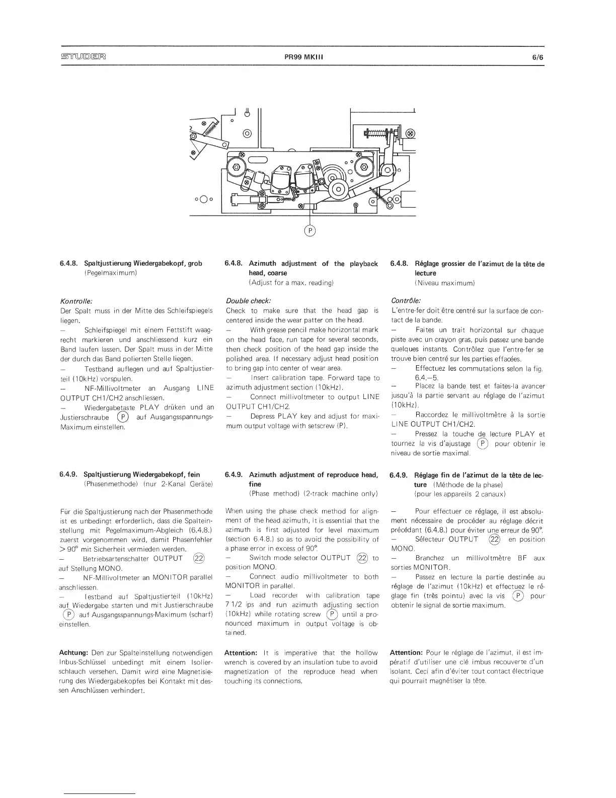
6.4.8.
Spaitjustierung Wiedergabekopf,
grob
(Pegelmaximum)
Kontrolle:
Der
Spalt
muss in
der Mitte des
Schleifspiegels
liegen.
—
Schleifspiegel
mit einem Fettstift waag-
recht
markieren
und
anschliessend
kurz ein
Band
laufen
lassen.
Der Spalt
muss in
der Mitte
der durch das
Band
polierten
Stelle liegen.
—
Testband
auflegen
und
auf
Spaltjustier-
teil
(1
OkHz)
vorspulen.
—
NF-Millivoltmeter
an
Ausgang
LINE
OUTPUT
CH1/CH2
anschliessen.
—
Wiedergabetaste
PLAY
druken und
an
Justierschraube
(p)
auf
Ausgangsspannungs-
Maximum
einstellen.
6.4.9.
Spaitjustierung
Wiedergabekopf, fein
(Phasenmethode) (nur
2-Kanal
Gerate)
Fur die
Spaitjustierung
nach der
Phasenmethode
ist es unbedingt
erforderlich, dass
die Spaltein-
stellung mit
Pegelmaximum-Abgleich
(6.4.8.)
zuerst vorgenommen wird,
damit Phasenfehler
>
90°
mit Sicherheit
vermieden
warden.
—
Betriebsartenschalter
OUTPUT
(2^
auf
Stellung
MONO.
—
NF-Millivoltmeter
an
MONITOR
parallel
anschliessen.
—
Testband auf
Spaitjustierteil
(10kHz)
auf
Wiedergabe
starten und
mit
Justierschraube
auf
Ausgangsspannungs-Maximum
(scharf)
einstellen.
Achtung:
Den
zur Spalteinstellung notwendigen
I
nbus-Schlussel
unbedingt mit einem Isolier-
schlauch
versehen.
Damit wird eine
Magnetisie-
rung
des
Wiedergabekopfes
bei Kontakt mjt des-
sen
Anschlussen
verhindert.
6.4.8.
Azimuth
adjustment
of the
playback
head,
coarse
(Adjust
for
a
max.
reading)
Double check:
Check to
make sure that
the head
gap
is
centered
inside the
wear patter on
the
head.
—
With grease pencil make
horizontal mark
on the head
face,
run
tape
for several seconds,
then check
position of the head gap
inside the
polished area.
If necessary adjust
head
position
to bring
gap
into center of wear area.
—
Insert calibration
tape. Forward
tape to
azimuth adjustment section
(10kHz).
—
Connect
millivoltmeter
to
output
LINE
OUTPUT CH1/CH2.
—
Depress
PLAY
key and adjust
for maxi-
mum
output voltage
with
setscrew
(P).
6.4.9.
Azimuth adjustment of reproduce
head,
fine
(Phase method)
(2-track machine only)
When
using the
phase
check
method for
align-
ment
of the
head azimuth,
it is
essential
that the
azimuth
is first
adjusted for level
maximum
(section
6.4.8.) so as to avoid
the possibility
of
a phase error in
excess of
90°.
—
Switch
mode
selector OUTPUT
to
position
MONO.
—
Connect
audio
millivoltmeter
to both
MONITOR
in parallel.
—
Load
recorder
with
calibration
tape
7
1/2 ips
and run
azimuth
adjusting
section
(10kHz)
while
rotating
screw
until
a pro-
nounced
maximum
in
output
voltage is
ob-
tained.
Attention:
It
is imperative that
the hollow
wrench is
covered
by
an insulation tube
to avoid
magnetization
of the reproduce
head when
touching its
connections.
6.4.8. Reglage
gross ier de
I'azimut
de
la t§te
de
lecture
(Niveau
maximum)
Contrdle:
L'entre-fer
doit
etre
centre
sur la
surface
de con-
tact de la
bande.
—
Faites
un trait
horizontal
sur chaque
piste avec
un
crayon
gras, puis
passez
une
bande
quelques
instants.
Controlez
que
l'entre-fer
se
trouve
bien centre
sur les
parties
effacees.
—
Effectuez
les
commutations
selon la fiq.
6.4.-5.
—
Placez
la bande
test et faites-la
avancer
jusqu'a la
partie servant
au reglage
de I'azimut
(10kHz).
—
Raccordez le
millivoltmetre
a
la sortie
LINE
OUTPUT
CH1/CH2.
—
Pressez
la
touche
de
lecture PLAY
et
tournez
la vis
d'ajustage
(J)
pour
obtenir le
niveau
de sortie
maximal.
6.4.9.
Reglage
fin de Tazimut
de la
tdte
de lec-
ture (Methode
de la phase)
(pour
les
appareils
2 canaux)
—
Pour
effectuer
ce
reglage, il
est
absolu-
ment
necessaire
de proceder
au reglage
decrit
precedant
(6.4.8.)
pour eviter
une
erreur
de
90°.
—
Selecteur
OUTPUT en position
MONO.
—
Branchez
un millivoltmetre BF
aux
sorties
MONITOR.
—
Passez
en lecture la partie destinee
au
reglage
de I'azimut (10kHz)
et effectuez le re-
glage
fin
(tr6s pointu)
avec la vis (F)
pour
obtenir le signal
de sortie maximum.
Attention:
Pour
le reglage de
I'azimut, il
est im-
peratif d'utiliser une
cle imbus
recouverte
d'un
isolant.
Oeci
afin d'eviter tout
contact
blectrique
qui pourrait
magnetiser la
tete.
 Loading...