/07.2016/G20
23
Gerät 51 71 91 131 151
Eintrittsleitung mm 28 28 28 28 28
Austrittsleitung mm 28 28 28 28 28
Gerät 51 71 91 131 151
Downflow
Kühlwasser-
Eintrittsleitung
Ix 441 441 441 456 456
Iy 118 118 118 120 120
Iz 76 76 76 51 76
Kühlwasser-
Austrittsleitung
Ox 461 461 461 476 476
Oy 189 189 189 190 190
Oz 76 76 76 51 76
Upflow
Kühlwasser-
Eintrittsleitung
Ix 440 440 440 456 456
Iy 121 121 121 122 122
Iz 76 76 76 76 76
Kühlwasser-
Austrittsleitung
Ox 460 460 460 476 476
Oy 191 191 191 192 192
Oz 76 76 76 76 76
Iy
Oy
Ix
Oz
Ox
Iz
32 187 46 144 46 85 32
x
z
y
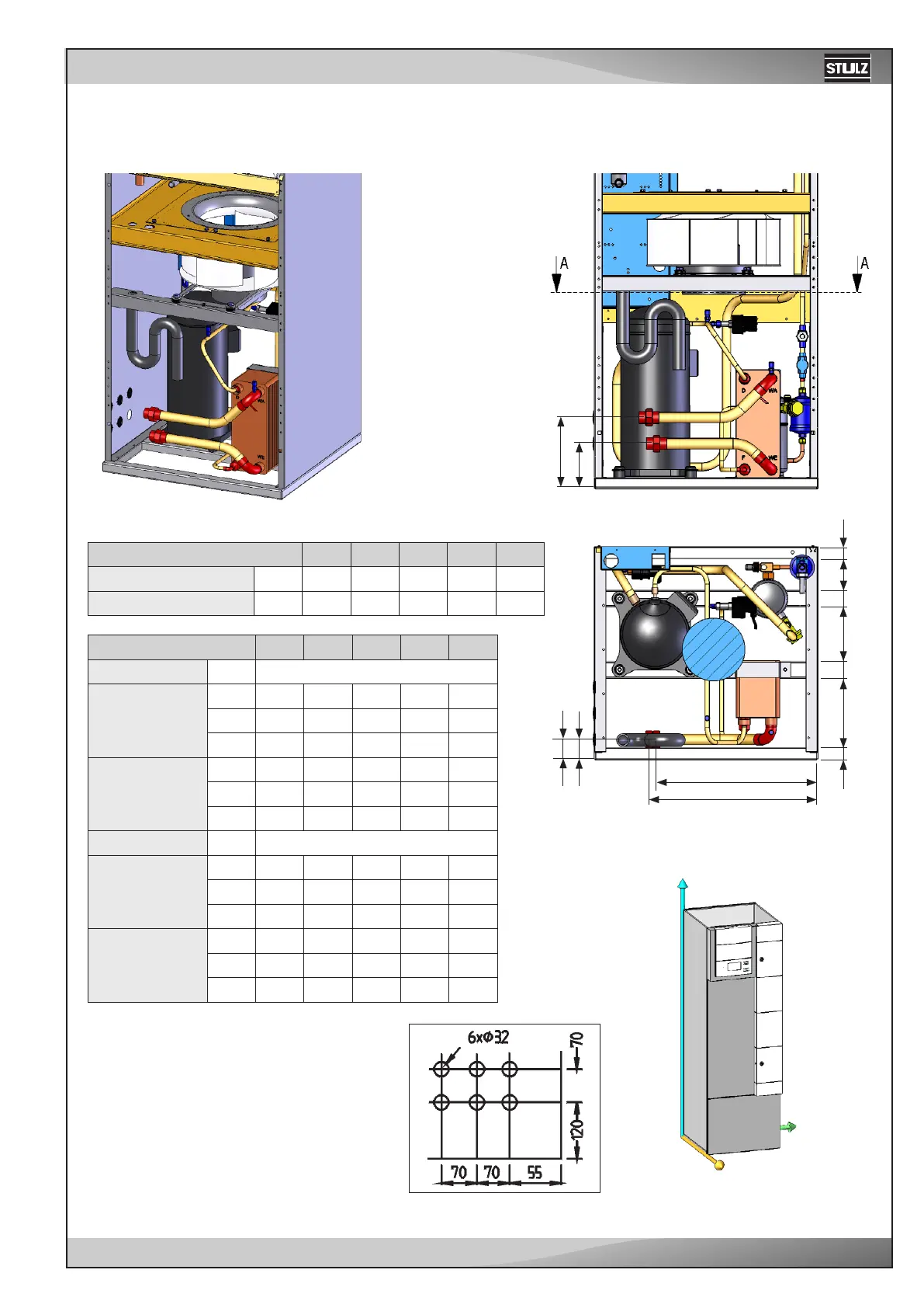
Downflow/Upflow - CCD/U 51/71/91/131/151 G
EN
To connect the piping notice the labels on the pipe ends.
Water pipe diameters
Rear view:
Rear view:
Section A-A
All dimensions in mm.
Unit
Inlet pipe mm
Outlet pipe mm
Unit
Downflow
Cooling water
inlet pipe
Ix
Iy
Iz
Cooling water
outlet pipe
Ox
Oy
Oz
Upflow
Cooling water
inlet pipe
Ix
Iy
Iz
Cooling water
outlet pipe
Ox
Oy
Oz
In general the pipes of downflow units are
routed through the raised floor out of the
unit. However you can route them through
openings in the right side panel. See the
position and dimension of the openings in
the right drawing. The point of reference is
the right, rear corner below.