Page 20
Electronic Control System
Wine Storage
Wine Storage
(400-
(400-
2
2
)
)
Series
Series
3-4
#3758410 - Revision C - May, 2014
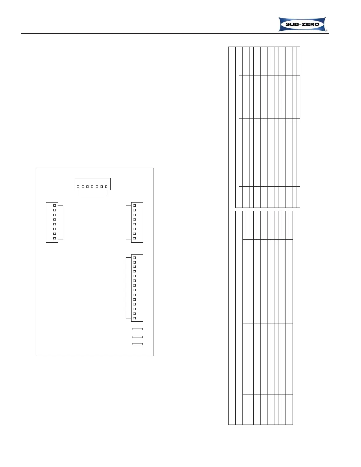
J3
CONTROL
BOARD
E3
14
E1
E2
WINE
J8
2
8
J1
J2
1
1
Figure 3-2. Control Board Layout
Figure 3-3. Control Board Summary Table
120 VOLT CIRCUITS
J3
P11
EMPTY
P13
EMPTY
P6 EMPTY
E1
POWER IN
POWER INTO BOARD
BLACK
E2
COMPRESSOR
POWERS COMPRESSOR
GRAY
CIRCUIT DESCRIPTION FUNCTION COLOR
P10 PINK
P14 GROUND EARTH GROUND GREEN/YELLOW
P12
NEUTRAL
NEUTRAL INTO BOARD
WHITE
E3 LIGHTS POWERS LIGHTS BROWN
DESCRIPTIONCIRCUIT FUNCTION COLOR
LOW VOLTAGE CIRCUITS
P1 LOWER CABINET SENSES TEMPERATURE BLUE/WHITE
J2 THERMISTER CIRCUITS
BLUE/WHITELOWER CABINETP2 SENSES TEMPERATURE
BLUE/BLACKUPPER CABINETP3 SENSES TEMPERATURE
BLUE/BLACKUPPER CABINETP4 SENSES TEMPERATURE
BLUE/REDLOWER EVAPORATORP5 SENSES TEMPERATURE
ORANGE/REDLOWER EVAPORATORP6 SENSES TEMPERATURE
BLUE/YELLOWUPPER EVAPORATORP7 SENSES TEMPERATURE
ORANGE/YELLUPPER EVAPORATORP8 SENSES TEMPERATURE
400 SERIES CONTROL BOARD SUMMARY/ LAYOUT
LOWER EVAP. FAN
P8 BLUE
COOLS LOWER COMPARTMENT
EMPTYP7
UPPER EVAP. FAN COOLS UPPER COMPARTMENT
LIGHTS OVERRIDEP9 ORANGEON WHEN LIGHTS ON 100%
P1 REFRIGERANT VALVE
P5
ALARM CIRCUIT-NORMALLY OPEN
P3
FOR HOME ALARMS
EMPTYP2
ALARM CIRCUIT-COMMON FOR HOME ALARMS
ALARM CIRCUIT-NORMALLY CLOSEDP4 FOR HOME ALARMS
WHT/RED
GRAY/WHT
WHT/BLUE
CONTROL REF
TAN
J3
WINE STORAGE CONTROL BOARD
LAYOUT AND SUMMARY TABLE
The electrical connection points on the wine storage control board
are labeled Alphanumerically. These labels correspond with the
alphanumeric control board summary layout table on the wiring dia-
gram. By referencing the table, it is possible to identify which com-
ponents are connected at which connection points on the control
board. Below is a layout diagram of the control board, followed by a
copy of a summary table. (See Figures 3-2 and 3-3)
NOTE: All components on the control board are non-replaceable. If
problems with the control board are identified, the complete control
board must be replaced.
 Loading...