7-12
Component Access / Removal
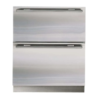
Built-In
Built-In
(600-
(600-
2
2
)
)
Series
Series
#3758407 - Revision B - August, 2006
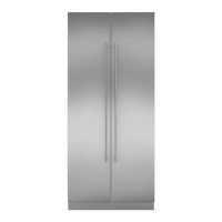
Door Assembly (601RG-2, 611G-2, 650G-2, 685-2
Refrigerator, 695-2 Refrigerator)
To remove a door, the door closer assembly must be
disconnected fist (excluding 611G-2 and 650G-2).
Door Closer Disconnection - To disconnect a door
closer (See Figure 7-26):
1. Open door until hole in bottom cabinet hinge aligns
with hole in door closer arm.
2. Insert short screwdriver up into the two holes.
NOTE: This screwdriver will be used to pry the
door closer arm back onto the door hinge stud.
3. Use a small straight-blade screwdriver to remove E-
ring which holds door closer arm to bottom door
hinge stud.
4. Pry door closer arm down off of door hinge stud.
Door Removal - To remove a door (See Figures 7-27
and 7-28):
1. Disconnect electrical leads at top cabinet hinge.
2. Extract top cabinet hinge mounting bolts.
3. Lean door away from unit and lift off of bottom cabi-
net hinge.
NOTE: When reinstalling door, use screwdriver in
cabinet hinge hole and door closer arm hole to pry
door closer arm back onto the door hinge stud.
Figure 7-26. Door Closer Disconnect
Remove
E-Ring
Pry down
Screwdriver
up into holes
Figure 7-28. Door
Lean door away
from unit and lift up
Figure 7-27. Door Electrical Leads
Electrical leads
Cabinet hinge
mounting bolts
REFRIGERATOR DOORS:
• ON GLASS DOOR MODELS HAVE HEATER
WIRES THAT PASS THROUGH TOP HINGE.
• ON MODELS 685-2 / 695-2 HAVE DISPENSER
WIRES THAT PASS THROUGH TOP HINGE.
FAILURE TO DISCONNECT THESE WIRES DURING
DOOR REMOVAL COULD CAUSE SERIOUS PER-
SONAL INJURY, AND/OR DAMAGE TO THE APPLI-
ANCE.